 | Info
Sheets |
| | | | | | | | | | | | | | | | | | | | | | | | |
 | Out-
side |
| | | | |
|
| | | | |
Result : Searchterm 'Image Acquisition Time' found in 1 term [ ] and 7 definitions [ ] and 7 definitions [ ], (+ 18 Boolean[ ], (+ 18 Boolean[ ] results ] results
| | previous 11 - 15 (of 26) nextResult Pages : [1] [2] [3 4 5 6] |  | |  | Searchterm 'Image Acquisition Time' was also found in the following service: | | | | |
| |  |
| |
|
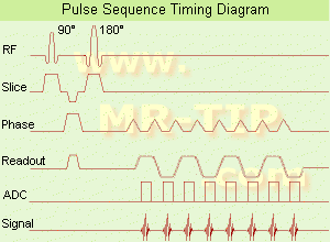
(EPI) Echo planar imaging is one of the early magnetic resonance imaging sequences (also known as Intascan), used in applications like diffusion, perfusion, and functional magnetic resonance imaging. Other sequences acquire one k-space line at each phase encoding step. When the echo planar imaging acquisition strategy is used, the complete image is formed from a single data sample (all k-space lines are measured in one repetition time) of a gradient echo or spin echo sequence (see single shot technique) with an acquisition time of about 20 to 100 ms.
The pulse sequence timing diagram illustrates an echo planar imaging sequence from spin echo type with eight echo train pulses. (See also Pulse Sequence Timing Diagram, for a description of the components.)
In case of a gradient echo based EPI sequence the initial part is very similar to a standard gradient echo sequence. By periodically fast reversing the readout or frequency encoding gradient, a train of echoes is generated.
EPI requires higher performance from the MRI scanner like much larger gradient amplitudes. The scan time is dependent on the spatial resolution required, the strength of the applied gradient fields and the time the machine needs to ramp the gradients.
In EPI, there is water fat shift in the phase encoding direction due to phase accumulations. To minimize water fat shift (WFS) in the phase direction fat suppression and a wide bandwidth (BW) are selected. On a typical EPI sequence, there is virtually no time at all for the flat top of the gradient waveform. The problem is solved by "ramp sampling" through most of the rise and fall time to improve image resolution.
The benefits of the fast imaging time are not without cost. EPI is relatively demanding on the scanner hardware, in particular on gradient strengths, gradient switching times, and receiver bandwidth. In addition, EPI is extremely sensitive to image artifacts and distortions. | | | | | | | | | | |  Further Reading: Further Reading: | Basics:
|
|
| |
| | | | | |
| |
|
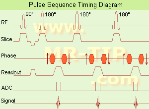
(FSE) In the pulse sequence timing diagram, a fast spin echo sequence with an echo train length of 3 is illustrated.
This sequence is characterized by a series of rapidly applied 180° rephasing pulses and multiple echoes, changing the phase encoding gradient for each echo.
The echo time TE may vary from echo to echo in the echo train. The echoes in the center of the K-space (in the case of linear k-space acquisition) mainly produce the type of image contrast, whereas the periphery of K-space determines the spatial resolution. For example, in the middle of K-space the late echoes of T2 weighted images are encoded. T1 or PD contrast is produced from the early echoes.
The benefit of this technique is that the scan duration with, e.g. a turbo spin echo turbo factor / echo train length of 9, is one ninth of the time. In T1 weighted and proton density weighted sequences, there is a limit to how large the ETL can be (e.g. a usual ETL for T1 weighted images is between 3 and 7). The use of large echo train lengths with short TE results in blurring and loss of contrast. For this reason, T2 weighted imaging profits most from this technique.
In T2 weighted FSE images, both water and fat are hyperintense. This is because the succession of 180° RF pulses reduces the spin spin interactions in fat and increases its T2 decay time. Fast spin echo (FSE) sequences have replaced conventional T2 weighted spin echo sequences for most clinical applications. Fast spin echo allows reduced acquisition times and enables T2 weighted breath hold imaging, e.g. for applications in the upper abdomen.
In case of the acquisition of 2 echoes this type of a sequence is named double fast spin echo / dual echo sequence, the first echo is usually density and the second echo is T2 weighted image. Fast spin echo images are more T2 weighted, which makes it difficult to obtain true proton density weighted images. For dual echo imaging with density weighting, the TR should be kept between 2000 - 2400 msec with a short ETL (e.g., 4).
Other terms for this technique are:
Turbo Spin Echo
Rapid Imaging Spin Echo,
Rapid Spin Echo,
Rapid Acquisition Spin Echo,
Rapid Acquisition with Refocused Echoes
| | | | | |
• View the DATABASE results for 'Fast Spin Echo' (31).
| | | | | | Further Reading: | | Basics:
|
|
News & More:
| |
| |
| | | | | |
| |
|
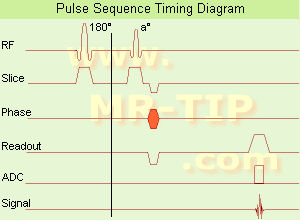
In simple ultrafast GRE imaging, TR and TE are so short, that tissues have a poor imaging signal and - more importantly - poor contrast except when contrast media enhanced ( contrast enhanced angiography). Therefore, the magnetization is 'prepared' during the preparation module, most frequently by an initial 180° inversion pulse.
In the pulse sequence timing diagram, the basic ultrafast gradient echo sequence is illustrated. The 180° inversion pulse is executed one time (to the left of the vertical line), the right side represents the data collection period and is often repeated depending on the acquisition parameters.
See also Pulse Sequence Timing Diagram, there you will find a description of the components.
Ultrafast GRE sequences have a short TR,TE, a low flip angle and TR is so short that image acquisition lasts less than 1 second and typically less than 500 ms. Common TR: 3-5 msec, TE: 2 msec, and the flip angle is about 5°.
Such sequences are often labeled with the prefix 'Turbo' like TurboFLASH, TurboFFE and TurboGRASS.
This allows one to center the subsequent ultrafast GRE data acquisition around the inversion time TI, where one of the tissues of interest has very little signal as its z-magnetization is passing through zero.
Unlike a standard inversion recovery (IR) sequence, all lines or a substantial segment of k-space image lines are acquired after a single inversion pulse, which can then together be considered as readout module. The readout module may use a variable flip angle approach, or the data acquisition may be divided into multiple segments (shots). The latter is useful particularly in cardiac imaging where acquiring all lines in a single segment may take too long relative to the cardiac cycle to provide adequate temporal resolution.
If multiple lines are acquired after a single pulse, the pulse sequence is a type of gradient echo echo planar imaging (EPI) pulse sequence. See also Magnetization Prepared Rapid Gradient Echo ( MPRAGE) and Turbo Field Echo ( TFE). | | | |
• View the DATABASE results for 'Ultrafast Gradient Echo Sequence' (13).
| | | | |
| | | Searchterm 'Image Acquisition Time' was also found in the following service: | | | | |
| | |
| |
|
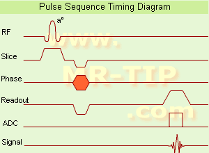
(GRE - sequence) A gradient echo is generated by using a pair of bipolar gradient pulses. In the pulse sequence timing diagram, the basic gradient echo sequence is illustrated. There is no refocusing 180° pulse and the data are sampled during a gradient echo, which is achieved by dephasing the spins with a negatively pulsed gradient before they are rephased by an opposite gradient with opposite polarity to generate the echo.
See also the Pulse Sequence Timing Diagram. There you will find a description of the components.
The excitation pulse is termed the alpha pulse α. It tilts the magnetization by a flip angle α, which is typically between 0° and 90°. With a small flip angle there is a reduction in the value of transverse magnetization that will affect subsequent RF pulses.
The flip angle can also be slowly increased during data acquisition (variable flip angle: tilt optimized nonsaturation excitation).
The data are not acquired in a steady state, where z-magnetization recovery and destruction by ad-pulses are balanced.
However, the z-magnetization is used up by tilting a little more of the remaining z-magnetization into the xy-plane for each acquired imaging line.
Gradient echo imaging is typically accomplished by examining the FID, whereas the read gradient is turned on for localization of the signal in the readout direction. T2* is the characteristic decay time constant associated with the FID. The contrast and signal generated by a gradient echo depend on the size of the longitudinal magnetization and the flip angle.
When α = 90° the sequence is identical to the so-called partial saturation or saturation recovery pulse sequence.
In standard GRE imaging, this basic pulse sequence is repeated as many times as image lines have to be acquired.
Additional gradients or radio frequency pulses are introduced with the aim to spoil to refocus the xy-magnetization at the moment when the spin system is subject to the next α pulse.
As a result of the short repetition time, the z-magnetization cannot fully recover and after a few initial α pulses there is an equilibrium established between z-magnetization recovery and z-magnetization reduction due to the α pulses.
Gradient echoes have a lower SAR, are more sensitive to field inhomogeneities and have a reduced crosstalk, so that a small or no slice gap can be used.
In or out of phase imaging depending on the selected TE (and field strength of the magnet) is possible.
As the flip angle is decreased, T1 weighting can be maintained by reducing the TR.
T2* weighting can be minimized by keeping the TE as short as possible, but pure T2 weighting is not possible.
By using a reduced flip angle, some of the magnetization value remains longitudinal (less time needed to achieve full recovery) and for a certain T1 and TR, there exist one flip angle that will give the most signal, known as the "Ernst angle".
Contrast values:
PD weighted: Small flip angle (no T1), long TR (no T1) and short TE (no T2*)
T1 weighted: Large flip angle (70°), short TR (less than 50ms) and short TE
T2* weighted: Small flip angle, some longer TR (100 ms) and long TE (20 ms)
Classification of GRE sequences can be made into four categories:
See also Gradient Recalled Echo Sequence, Spoiled Gradient Echo Sequence, Refocused Gradient Echo Sequence, Ultrafast Gradient Echo Sequence.
| | | | | |
• View the DATABASE results for 'Gradient Echo Sequence' (70).
| | | | | | Further Reading: | | Basics:
|
|
News & More:
| |
| |
| | | | | |
| |
|
Contrast enhanced MRI is a commonly used procedure in magnetic resonance imaging. The need to more accurately characterize different types of lesions and to detect all malignant lesions is the main reason for the use of intravenous contrast agents.
Some methods are available to improve the contrast of different tissues. The focus of dynamic contrast enhanced MRI (DCE-MRI) is on contrast kinetics with demands for spatial resolution dependent on the application. DCE- MR imaging is used for diagnosis of cancer (see also liver imaging, abdominal imaging, breast MRI, dynamic scanning) as well as for diagnosis of cardiac infarction (see perfusion imaging, cardiac MRI). Quantitative DCE-MRI requires special data acquisition techniques and analysis software.
Contrast enhanced magnetic resonance angiography (CE-MRA) allows the visualization of vessels and the temporal resolution provides a separation of arteries and veins. These methods share the need for acquisition methods with high temporal and spatial resolution.
Double contrast administration (combined contrast enhanced (CCE) MRI) uses two contrast agents with complementary mechanisms e.g., superparamagnetic iron oxide to darken the background liver and gadolinium to brighten the vessels. A variety of different categories of contrast agents are currently available for clinical use.
Reasons for the use of contrast agents in MRI scans are:
•
Relaxation characteristics of normal and pathologic tissues are not always different enough to produce obvious differences in signal intensity.
•
Pathology that is some times occult on unenhanced images becomes obvious in the presence of contrast.
•
Enhancement significantly increases MRI sensitivity.
•
In addition to improving delineation between normal and abnormal tissues, the pattern of contrast enhancement can improve diagnostic specificity by facilitating characterization of the lesion(s) in question.
•
Contrast can yield physiologic and functional information in addition to lesion delineation.
Common Indications:
Brain MRI : Preoperative/pretreatment evaluation and postoperative evaluation of brain tumor therapy, CNS infections, noninfectious inflammatory disease and meningeal disease.
Spine MRI : Infection/inflammatory disease, primary tumors, drop metastases, initial evaluation of syrinx, postoperative evaluation of the lumbar spine: disk vs. scar.
Breast MRI : Detection of breast cancer in case of dense breasts, implants, malignant lymph nodes, or scarring after treatment for breast cancer, diagnosis of a suspicious breast lesion in order to avoid biopsy.
For Ultrasound Imaging (USI) see Contrast Enhanced Ultrasound at Medical-Ultrasound-Imaging.com.
See also Blood Pool Agents, Myocardial Late Enhancement, Cardiovascular Imaging, Contrast Enhanced MR Venography, Contrast Resolution, Dynamic Scanning, Lung Imaging, Hepatobiliary Contrast Agents, Contrast Medium and MRI Guided Biopsy. | | | | | | | | | | |
• View the DATABASE results for 'Contrast Enhanced MRI' (14).
| | |
• View the NEWS results for 'Contrast Enhanced MRI' (8).
| | | | | | Further Reading: | Basics:
|
|
News & More:
|  |
FDA Approves Gadopiclenol for Contrast-Enhanced Magnetic Resonance Imaging
Tuesday, 27 September 2022 by www.pharmacytimes.com | | |
Effect of gadolinium-based contrast agent on breast diffusion-tensor imaging
Thursday, 6 August 2020 by www.eurekalert.org | | |
Artificial Intelligence Processes Provide Solutions to Gadolinium Retention Concerns
Thursday, 30 January 2020 by www.itnonline.com | | |
Accuracy of Unenhanced MRI in the Detection of New Brain Lesions in Multiple Sclerosis
Tuesday, 12 March 2019 by pubs.rsna.org | | |
The Effects of Breathing Motion on DCE-MRI Images: Phantom Studies Simulating Respiratory Motion to Compare CAIPIRINHA-VIBE, Radial-VIBE, and Conventional VIBE
Tuesday, 7 February 2017 by www.kjronline.org | | |
Novel Imaging Technique Improves Prostate Cancer Detection
Tuesday, 6 January 2015 by health.ucsd.edu | | |
New oxygen-enhanced MRI scan 'helps identify most dangerous tumours'
Thursday, 10 December 2015 by www.dailymail.co.uk | | |
All-organic MRI Contrast Agent Tested In Mice
Monday, 24 September 2012 by cen.acs.org | | |
A groundbreaking new graphene-based MRI contrast agent
Friday, 8 June 2012 by www.nanowerk.com |
|
| |
| | | | |
| | | |
|
| |
 | Look
Ups |
| |


