 | Info
Sheets |
| | | | | | | | | | | | | | | | | | | | | | | | |
 | Out-
side |
| | | | |
|
| | | | | |  | Searchterm 'View' was also found in the following services: | | | | |
|  |  |
| |
|
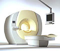
From Philips Medical Systems;
the Intera 3 T high field system, the first with a compact magnet, which is built on the same platform as the 1.5 T, is targeted to high-end neurological, orthopedic and cardiovascular imaging applications with maximum patient comfort and acceptance without compromising image quality and clinical performance. Useable for clinical routine and research.
The Intera systems offer diffusion tensor imaging ( DTI) fiber tracking that measures movement of water in the brain and can therefore detect areas of the brain where normal movement of water is disrupted.
Device Information and Specification
CLINICAL APPLICATION
Whole body
CONFIGURATION
Short bore compact
Standard: head, body, C1, C3; Optional: Small joint, flex-E, flex-R, endocavitary (L and S), dual TMJ, knee, neck, T/L spine, breast; Optional phased array: spine;; Optional SENSE coils: Flex body, flex cardiac, neuro-vascular, head
SE, Modified-SE, IR (T1, T2, PD), STIR, FLAIR, SPIR, FFE, T1-FFE, T2-FFE, Balanced FFE, TFE, Balanced TFE, Dynamic, Keyhole, 3D, Multi Chunk 3D, Multi Stack 3D, K Space Shutter, MTC, TSE, Dual IR, DRIVE, EPI, Cine, 2DMSS, DAVE, Mixed Mode; Angiography: Inflow MRA, TONE, PCA, CE MRA
TR
Min. 1.6 (Master) msec
TE
Min. 0.5 (Master) msec
Rapid View Recon. greater than 500 @ 256 Matrix
0.1 mm (Omni), 0.05 mm (Power)
128 x 128, 256 x 256,512 x 512,1024 x 1024 (64 for Bold img)
Variable in 1% increments
Lum.: 120 cd/m2; contrast: 150:1
Variable (op. param. depend.)
POWER REQUIREMENTS
380/400 V
STRENGTH
30 (Master) mT/m
| | | | | |
| | | Searchterm 'View' was also found in the following services: | | | | |
| | |
| |
|
MRI of the lumbar spine, with its multiplanar 3 dimensional imaging capability, is currently the preferred modality for establishing a diagnosis. MRI scans and magnetic resonance myelography have many advantages compared with computed tomography and/or X-ray myelography in evaluating the lumbar spine. MR imaging scans large areas of the spine without ionizing radiation, is noninvasive, not affected by bone artifacts, provides vascular imaging capability, and makes use of safer contrast agents ( gadolinium chelate).
Due to the high level of tissue contrast resolution, nerves and discs are clearly visible. MRI is excellent for detecting degenerative disease in the spine. Lumbar spine MRI accurately shows disc disease (prolapsed disc or slipped disc), the level at which disc disease occurs, and if a disc is compressing spinal nerves. Lumbar spine MRI depicts soft tissues, including the cauda equina, spinal cord, ligaments, epidural fat, subarachnoid space, and intervertebral discs. Loss of epidural fat on T1 weighted images, loss of cerebrospinal fluid signal around the dural sac on T2 weighted images and degenerative disc disease are common features of lumbar stenosis.
Common indications for MRI of the lumbar spine:
•
Neurologic deficits, evidence of radiculopathy, acute spinal cord compression (e.g., sudden bowel/bladder disturbance)
•
Suspected systemic disorders (primary tumors, drop metastases, osteomyelitis)
•
Postoperative evaluation of lumbar spine: disk vs. scar
•
Localized back pain with no radiculopathy (leg pain)
Lumbar spine imaging requires a special spine coil. often used whole spine array coils have the advantage that patients do not need other positioning if also upper parts of the spine should be scanned. Sagittal T1 and T2 weighted FSE sequences are the standard views. With multi angle oblique techniques individually oriented transverse images of each intervertebral disc at different angles can be obtained.
See also the related poll result: ' MRI will have replaced 50% of x-ray exams by' | | | | | |
• View the DATABASE results for 'Lumbar Spine MRI' (6).
| | | | |  Further Reading: Further Reading: | | Basics:
|
|
News & More:
| |
| |
| | | | | |
| |
|
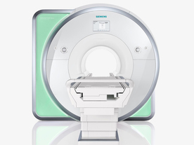
From Siemens Medical Systems;
Received FDA clearance in 2010.
The MAGNETOM Aera is a patient friendly, comfortable 1.5 Tesla MRI system with advanced radio frequency chain.
The system is equipped with the Tim 4G and Dot system (Total imaging matrix + Day optimizing throughput), to enhance both productivity and image quality.
Tim 4G technology provides improved SNR. The standard system configuration of 48 radio frequency channels and 204 coil elements creates an imaging matrix that allows maximum use of coil elements at full field of view. Dot provides improved image consistency through new features like auto align, auto FoV and automatic bolus detection.
Device Information and Specification
CLINICAL APPLICATION
Whole body
Head, spine, torso/ body coil, neurovascular, cardiac, neck, shoulder, knee, wrist, foot//ankle and multi-purpose flex coils. Peripheral vascular, breast, shoulder. Up to 60% more SNR with Tim 4G.
CHANNELS (min. / max. configuration)
48, 64
MINIMUM TE
3-D GRE: 0.22 (256 matrix), Ultra-short TE
At isocenter: L-R 70 cm, A-P (with table) 55 cm
MAGNET WEIGHT (gantry included)
3121 kg
DIMENSION H*W*D (gantry included)
145 x 231 x 219 cm
MAX. AMPLITUDE
33 or 45 mT/m
3 linear with 20 coils, 5 nonlinear 2nd-order
POWER REQUIREMENTS
380 / 400 / 420 / 440 / 460 / 480 V, 3-phase + ground; 85 kVA
| | | | | |
| | | Searchterm 'View' was also found in the following services: | | | | |
| | |
| |
|
Quick Overview
DESCRIPTION
Increase of the T2 time, bright signal in tendons
HELP
Angle not about 55°
The magic angle is a precisely defined angle, the value is approximately 54.7°. Hence, two nuclei with a dipolar coupling vector at an angle of approximately 54.7° to a strong external magnetic field have zero dipolar coupling.
Magic angle spinning is a technique in solid-state NMR spectroscopy, which employs this principle to remove or reduce dipolar couplings, thereby increasing spectral resolution.
In MRI, the magic angle effect visualizes as bright spots through an increased T2 time on short echo time (TE) images, for e.g. collagen fibers of tendons and ligaments, which are oriented at the magic angle of approximately 54.7° to the magnetic field.

Image Guidance
Take care that tendons and ligaments are not oriented at about a 54.7° angle to the main magnetic field. | | | | | | | Further Reading: | Basics:
|
|
| |
| | | Searchterm 'View' was also found in the following services: | | | | |
| | |
| |
|
( MRCP) This MR imaging technique takes advantage of the high signal intensity of body fluids and acquires heavy T2 weighted images of the gall bladder, the pancreas and parts of the liver. Due to the T2 weighting, the liver and other solid parenchyma are signal suppressed and only fluid-filled structures in addition to the gall bladder, the bile and pancreatic ducts retain important signal intensity.
Hepatobiliary contrast agents (e.g. Gadoxetic Acid, CMC 001) can be useful for enhancement of the bile ducts and better imaging of the biliary tract.
A 2D cholangiogram, often only one thick slice (a volume with a thickness of 4 - 8 cm, mostly coronal planned) or 5 - 6 radial placed slices, shows a view like single slices. If a 3D acquisition is used, the postprocessing function maximum intensity projection ( MIP) can show reconstructions from multiple sides. | | | | | | | | |
• View the DATABASE results for 'Magnetic Resonance Cholangiopancreaticography' (3).
| | | | | | Further Reading: | News & More:
|
|
| |
| | | | |
| | |
| | | |
|
| |
 | Look
Ups |
| |


