| Info
Sheets |
| | | | | | | | | | | | | | | | | | | | | | | | |
 | Out-
side |
| | | | |
|
| | | | | |  | Searchterm 'epi' was also found in the following services: | | | | |
|  | | | | | |  |
| |
|
Paramagnetic substances, for example Gd-DTPA solutions, are used as MRI oral contrast agents in gastrointestinal imaging to d epict the lumen of the digestive organs. Different Gd-DTPA solutions or zeolites containing gadolinium can be used e.g., for diagnosis of delayed gastric emptying, diagnosis of Crohn's disease etc.
Low concentrations of gastrointestinal paramagnetic contrast agents cause a reduction in T1 relaxation time; consequently, these agents act on T1 weighted images by increasing the signal intensity of the bowel lumen. High concentrations cause T2 shortening by decreasing the signal, similar to superparamagnetic iron oxide.
Gd-DTPA chelates are unstable at the low pH in the stomach, therefore buffering is necessary for oral use.
See also Gadopentetate Gastrointestinal, Gadolinium Zeolite, Negative Oral Contrast Agents, Gastrointestinal Superparamagnetic Contrast Agents, and Ferric ammonium citrate. | | | | | |
• View the DATABASE results for 'Gastrointestinal Paramagnetic Contrast Agents' (5).
| | | | |
| | | | | |
| |
|
(GRE - sequence) A gradient echo is generated by using a pair of bipolar gradient pulses. In the pulse sequence timing diagram, the basic gradient echo sequence is illustrated. There is no refocusing 180° pulse and the data are sampled during a gradient echo, which is achieved by dephasing the spins with a negatively pulsed gradient before they are rephased by an opposite gradient with opposite polarity to generate the echo.
See also the Pulse Sequence Timing Diagram. There you will find a description of the components.
The excitation pulse is termed the alpha pulse α. It tilts the magnetization by a flip angle α, which is typically between 0° and 90°. With a small flip angle there is a reduction in the value of transverse magnetization that will affect subsequent RF pulses.
The flip angle can also be slowly increased during data acquisition (variable flip angle: tilt optimized nonsaturation excitation).
The data are not acquired in a steady state, where z-magnetization recovery and destruction by ad-pulses are balanced.
However, the z-magnetization is used up by tilting a little more of the remaining z-magnetization into the xy-plane for each acquired imaging line.
Gradient echo imaging is typically accomplished by examining the FID, whereas the read gradient is turned on for localization of the signal in the readout direction. T2* is the characteristic decay time constant associated with the FID. The contrast and signal generated by a gradient echo depend on the size of the longitudinal magnetization and the flip angle.
When α = 90° the sequence is identical to the so-called partial saturation or saturation recovery pulse sequence.
In standard GRE imaging, this basic pulse sequence is repeated as many times as image lines have to be acquired.
Additional gradients or radio frequency pulses are introduced with the aim to spoil to refocus the xy-magnetization at the moment when the spin system is subject to the next α pulse.
As a result of the short repetition time, the z-magnetization cannot fully recover and after a few initial α pulses there is an equilibrium established between z-magnetization recovery and z-magnetization reduction due to the α pulses.
Gradient echoes have a lower SAR, are more sensitive to field inhomogeneities and have a reduced crosstalk, so that a small or no slice gap can be used.
In or out of phase imaging depending on the selected TE (and field strength of the magnet) is possible.
As the flip angle is decreased, T1 weighting can be maintained by reducing the TR.
T2* weighting can be minimized by ke eping the TE as short as possible, but pure T2 weighting is not possible.
By using a reduced flip angle, some of the magnetization value remains longitudinal (less time needed to achieve full recovery) and for a certain T1 and TR, there exist one flip angle that will give the most signal, known as the "Ernst angle".
Contrast values:
PD weighted: Small flip angle (no T1), long TR (no T1) and short TE (no T2*)
T1 weighted: Large flip angle (70°), short TR (less than 50ms) and short TE
T2* weighted: Small flip angle, some longer TR (100 ms) and long TE (20 ms)
Classification of GRE sequences can be made into four categories:
See also Gradient Recalled Echo Sequence, Spoiled Gradient Echo Sequence, Refocused Gradient Echo Sequence, Ultrafast Gradient Echo Sequence.
| | | | | |
• View the DATABASE results for 'Gradient Echo Sequence' (70).
| | | | |  Further Reading: Further Reading: | | Basics:
|
|
News & More:
| |
| |
| | | Searchterm 'epi' was also found in the following services: | | | | |
| | |
| |
|
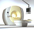
From Philips Medical Systems;
Philips Infinion 1.5 T is designed to maximize the efficiency and quality of patient care. Developed with the patient in mind, the Infinion is the shortest and most open 1.5T scanner available. The unique 'ultra short' 1.4 m magnet assures patient comfort and acceptance without compromising image quality and clinical performance.
Device Information and Specification
CLINICAL APPLICATION
Whole body
CONFIGURATION
Ultra short bore
Head, head / neck, integrated C-spine, L/T spine array, small large GP coils, body flex array, torso pelvis array, breast array, endocavitary, shoulder array, lower extremity, hand / wrist, cardiac, PV array
SE, TSE, SS TSE, EPI, IR, STIR, FLAIR, FFE, TFE, T1 TFE, T2 TFE, Presat, Fatsat, MTC, Diff-opt., Angiography: PCA, MCA, TOF
IMAGING MODES
Single slice, single volume, multi slice, multi volume
80 images/sec std.; up to320 opt.@256
H*W*D
233 (lead fitted) x 198 x 140 cm
POWER REQUIREMENTS
400/480 V
COOLING SYSTEM TYPE
Closed loop, chilled water
| | | |
• View the DATABASE results for 'Infinion 1.5T™' (2).
| | | | |
| | | | | |
| |
|
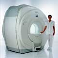
Device Information and Specification
CLINICAL APPLICATION
Whole body
CONFIGURATION
Short bore compact
Standard: head, body, C1, C3; Optional: Small joint, flex-E, flex-R, endocavitary (L and S), dual TMJ, knee, neck, T/L spine, breast; Optional phased array: Spine, pediatric, 3rd party connector, Optional SENSE Coils: Flex-S-M-L, Flex Body, Flex Cardiac
SE, Modified-SE, IR (T1, T2, PD), STIR, FLAIR, SPIR, FFE, T1-FFE, T2-FFE, Balanced FFE, TFE, Balanced TFE, Dynamic, Keyhole, 3D, Multi Chunk 3D, Multi Stack 3D, K Space Shutter, MTC, TSE, Dual IR, DRIVE, EPI, Cine, 2DMSS, DAVE, Mixed Mode; Angiography: Inflow MRA, TONE, PCA, CE MRA
TR
Min. 2.9 (Omni) msec, 1.6 (Power) msec
TE
Min. 1.0 (Omni) msec, 0.7 (Power) msec
RapidView Recon. greater than 500 @ 256 Matrix
0.1 mm(Omni), 0.05 mm (Power)
128 x 128, 256 x 256,512 x 512,1024 x 1024 (64 for Bold img)
Variable in 1% increments
Lum.: 120 cd/m2; contrast: 150:1
Variable (op. param. depend.)
POWER REQUIREMENTS
380/400 V
STRENGTH
23 mT/m (Omni), 30 (Power) mT/m
| | | |
• View the DATABASE results for 'Intera 1.0T™' (2).
| | | | |
| | | | |
| | | |
|
| |
 | Look
Ups |
| |