 | Info
Sheets |
| | | | | | | | | | | | | | | | | | | | | | | | |
 | Out-
side |
| | | | |
|
| | | 'Fast Spin Echo Sequence' | |
Result : Searchterm 'Fast Spin Echo Sequence' found in 0 term [ ] and 7 definitions [ ] and 7 definitions [ ], (+ 16 Boolean[ ], (+ 16 Boolean[ ] results ] results
| | previous 6 - 10 (of 23) nextResult Pages : [1 2] [3 4 5] |  | | | | |  |
| |
|
Quick Overview
Materials with magnetic susceptibility cause this artifact. There are in general three kinds of materials with magnetic susceptibility: ferromagnetic materials (iron, nickel etc.) with a strong influence and paramagnetic/diamagnetic (aluminium, platinum etc./gold, water, most organic compounds etc.) materials with a minimal/non influence on magnetic fields. In MRI, susceptibility artifacts are caused for example by medical devices in or near the magnetic field or by implants of the patient. These materials with magnetic susceptibility distort the linear magnetic field gradients, which results in bright areas (misregistered signals) and dark areas (no signal) nearby the magnetic material.

Image Guidance
| | | | | | | | | | |  Further Reading: Further Reading: | | Basics:
|
|
News & More:
| |
| |
| | | | | |
| |
|
| | | | | | | Further Reading: | News & More:
|
|
| |
| | | | |  |
| |
|
(SE) The most common pulse sequence used in MR imaging is based of the detection of a spin or Hahn echo. It uses 90° radio frequency pulses to excite the magnetization and one or more 180° pulses to refocus the spins to generate signal echoes named spin echoes (SE).
In the pulse sequence timing diagram, the simplest form of a spin echo sequence is illustrated.
The 90° excitation pulse rotates the longitudinal magnetization ( Mz) into the xy-plane and the dephasing of the transverse magnetization (Mxy) starts.
The following application of a 180° refocusing pulse (rotates the magnetization in the x-plane) generates signal echoes. The purpose of the 180° pulse is to rephase the spins, causing them to regain coherence and thereby to recover transverse magnetization, producing a spin echo.
The recovery of the z-magnetization occurs with the T1 relaxation time and typically at a much slower rate than the T2-decay, because in general T1 is greater than T2 for living tissues and is in the range of 100-2000 ms.
The SE pulse sequence was devised in the early days of NMR days by Carr and Purcell and exists now in many forms: the multi echo pulse sequence using single or multislice acquisition, the fast spin echo (FSE/TSE) pulse sequence, echo planar imaging (EPI) pulse sequence and the gradient and spin echo (GRASE) pulse sequence;; all are basically spin echo sequences.
In the simplest form of SE imaging, the pulse sequence has to be repeated as many times as the image has lines. Contrast values:
PD weighted: Short TE (20 ms) and long TR.
T1 weighted: Short TE (10-20 ms) and short TR (300-600 ms)
T2 weighted: Long TE (greater than 60 ms) and long TR (greater than 1600 ms)
With spin echo imaging no T2* occurs, caused by the 180° refocusing pulse. For this reason, spin echo sequences are more robust against e.g., susceptibility artifacts than gradient echo sequences.
See also Pulse Sequence Timing Diagram to find a description of the components.
| | | | | |
• View the DATABASE results for 'Spin Echo Sequence' (24).
| | | | | | Further Reading: | | Basics:
|
|
News & More:
| |
| |
| | | | | |
| |
|
(EPI) Echo planar imaging is one of the early magnetic resonance imaging sequences (also known as Intascan), used in applications like diffusion, perfusion, and functional magnetic resonance imaging. Other sequences acquire one k-space line at each phase encoding step. When the echo planar imaging acquisition strategy is used, the complete image is formed from a single data sample (all k-space lines are measured in one repetition time) of a gradient echo or spin echo sequence (see single shot technique) with an acquisition time of about 20 to 100 ms.
The pulse sequence timing diagram illustrates an echo planar imaging sequence from spin echo type with eight echo train pulses. (See also Pulse Sequence Timing Diagram, for a description of the components.)
In case of a gradient echo based EPI sequence the initial part is very similar to a standard gradient echo sequence. By periodically fast reversing the readout or frequency encoding gradient, a train of echoes is generated.
EPI requires higher performance from the MRI scanner like much larger gradient amplitudes. The scan time is dependent on the spatial resolution required, the strength of the applied gradient fields and the time the machine needs to ramp the gradients.
In EPI, there is water fat shift in the phase encoding direction due to phase accumulations. To minimize water fat shift (WFS) in the phase direction fat suppression and a wide bandwidth (BW) are selected. On a typical EPI sequence, there is virtually no time at all for the flat top of the gradient waveform. The problem is solved by "ramp sampling" through most of the rise and fall time to improve image resolution.
The benefits of the fast imaging time are not without cost. EPI is relatively demanding on the scanner hardware, in particular on gradient strengths, gradient switching times, and receiver bandwidth. In addition, EPI is extremely sensitive to image artifacts and distortions. | | | |
• View the DATABASE results for 'Echo Planar Imaging' (19).
| | |
• View the NEWS results for 'Echo Planar Imaging' (1).
| | | | | | Further Reading: | Basics:
|
|
| |
| | | | | |
| |
|
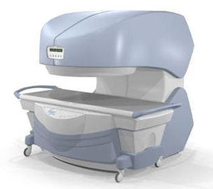
From
Millennium Technology Inc.
This open C-shaped MRI system eases patient comfort and technologist maneuverability. This low cost scanner is build for a wide range of applications. The Virgo™ patient table is detachable and moves on easy rolling castors. Able to accommodate patient weights up to 160 kg, the tabletop has a range of motion of 30 cm in the lateral direction and 90cm in the longitudinal direction. Images generated with this scanner can only be viewed (without data loss) on Millennium's proprietary viewing software.
Device Information and Specification CLINICAL APPLICATION Whole body Head, Body, Neck, Knee, Shoulder,
Spine, Wrist, Breast, Extremity, Lumbar Spine, TMJ
IMAGING MODES Localizer, single slice, multislice, volume, fast, POMP, multi slab, cine, slice and frequency zip, extended dynamic range, tailored RF | | | | | |
| | | | |
| | | |
|
| |
 | Look
Ups |
| |


