 | Info
Sheets |
| | | | | | | | | | | | | | | | | | | | | | | | |
 | Out-
side |
| | | | |
|
| | | 'Gradient Magnetic Field' | |
Result : Searchterm 'Gradient Magnetic Field' found in 2 terms [ ] and 7 definitions [ ] and 7 definitions [ ], (+ 18 Boolean[ ], (+ 18 Boolean[ ] results ] results
| | previous 11 - 15 (of 27) nextResult Pages : [1] [2] [3 4 5 6] |  | |  | Searchterm 'Gradient Magnetic Field' was also found in the following services: | | | | |
| |  |
| |
|
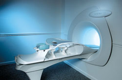
From Aurora Imaging Technology, Inc.;
The Aurora® 1.5T Dedicated Breast MRI System with Bilateral SpiralRODEO™ is the first and only FDA approved MRI device designed specifically for breast imaging. The Aurora System, which is already in clinical use at a growing number of leading breast care centers in the US, Europe, got in December 2006 also the approval from the State Food and Drug Administration of the People's Republic of China (SFDA).
'Some of the proprietary and distinguishing features of the Aurora System include: 1) an ellipsoid magnetic shim that provides coverage of both breasts, the chest wall and bilateral axillary lymph nodes; 2) a precision gradient coil with the high linearity required for high resolution spiral reconstruction;; 3) a patient-handling table that provides patient comfort and procedural utility; 4) a fully integrated Interventional System for MRI guided biopsy and localization; and 5) the user-friendly AuroraCAD™ computer-aided image display system designed to improve the accuracy and efficiency of diagnostic interpretations.'
Device Information and Specification
CONFIGURATION
Short bore compact
TE
From 5 ms for RODEO Plus to over 80 ms, 120 ms for T2 sequences
Around 0.02 sec for a 256x256 image, 12.4 sec for a 512 x 512 x 32 multislice set
20 - 36 cm, max. elliptical 36 x 44 cm
POWER REQUIREMENTS
150A/120V-208Y/3 Phase//60 Hz/5 Wire
| | | | | | | | | | |  Further Reading: Further Reading: | News & More:
|
|
| |
| | | | | |
| |
|

If a device is to be labeled MR Safe, the following information should be provided:
•
Data demonstrating that when the device is introduced or used in the MRI environment (i.e. the MRI scan room) it does not pose an increased safety risk to the patient or other personnel,
•
a scientifically-based rationale for why data are not necessary to prove the safety of the device in the MR environment (for example, a passive device made entirely of a polymer known to be nonreactive in strong magnetic fields).
If a device is to be labeled MR Compatible, the following information should be provided:
•
Data demonstrating that when the device is introduced or used in the MRI environment, it is MR safe that it performs its intended function without performance degradation, and that it does not adversely affect the function of the MRI scanner (e.g. no significant image artifacts or noise). Any image artifact or noise due to the medical device should be quantified (e.g., % volume affected, signal to noise ratio),
•
a scientifically-based rationale for why data are not necessary to prove the compatibility of the device in the MRI environment.
Test Conditions:
The static magnetic field strength ( Gauss (G) or Tesla (T)) to which the device was tested and demonstrated to be MRI 'safe', 'compatible', or 'intended for use in' should be related to typical machine ratings (e.g. 0.5 T, 1.5 T, 2.0 T, and shielded or unshielded magnet, etc).
The same conditions should be used for the spatial gradient ( field strength per unit distance (i.e., G/cm)) in which the device was tested and demonstrated to be 'safe', 'compatible', or 'intended for use in'.
Also the RF transmitter power used during testing of the device, should be related to this typical machine ratings. | | | |
• View the DATABASE results for 'MR Compatibility' (4).
| | |
• View the NEWS results for 'MR Compatibility' (2).
| | | | | | Further Reading: | | Basics:
|
|
News & More:
| |
| |
| | | | | |
| |
|
•
In the 1930's, Isidor Isaac Rabi (Columbia University) succeeded in detecting and measuring single states of rotation of atoms and molecules, and in determining the mechanical and magnetic moments of the nuclei.
•
Felix Bloch (Stanford University) and Edward Purcell (Harvard University) developed instruments, which could measure the magnetic resonance in bulk material such as liquids and solids. (Both honored with the Nobel Prize for Physics in 1952.) [The birth of the NMR spectroscopy]
•
In the early 70's, Raymond Damadian (State University of New York) demonstrated with his NMR device, that there are different T1 relaxation times between normal and abnormal tissues of the same type, as well as between different types of normal tissues.
•
In 1973, Paul Lauterbur (State University of New York) described a new imaging technique that he termed Zeugmatography. By utilizing gradients in the magnetic field, this technique was able to produce a two-dimensional image (back-projection). (Through analysis of the characteristics of the emitted radio waves, their origin could be determined.) Peter Mans field further developed the utilization of gradients in the magnetic field and the mathematically analysis of these signals for a more useful imaging technique. (Paul C Lauterbur and Peter Mans field were awarded with the 2003 Nobel Prize in Medicine.)
•
1977/78: First images could be presented.
A cross section through a finger by Peter Mansfield and Andrew A. Maudsley.
Peter Mansfield also could present the first image through the abdomen.
•
In 1977, Raymond Damadian completed (after 7 years) the first MR scanner (Indomitable). In 1978, he founded the FONAR Corporation, which manufactured the first commercial MRI scanner in 1980. Fonar went public in 1981.
•
1981: Schering submitted a patent application for Gd-DTPA dimeglumine.
•
1982: The first 'magnetization-transfer' imaging by Robert N. Muller.
•
In 1983, Toshiba obtained approval from the Ministry of Health and Welfare in Japan for the first commercial MRI system.
•
1986: Jürgen Hennig, A. Nauerth, and Hartmut Friedburg (University of Freiburg) introduced RARE (rapid acquisition with relaxation enhancement) imaging. Axel Haase, Jens Frahm, Dieter Matthaei, Wolfgang Haenicke, and Dietmar K. Merboldt (Max-Planck-Institute, Göttingen) developed the FLASH ( fast low angle shot) sequence.
•
1988: Schering's MAGNEVIST gets its first approval by the FDA.
•
In 1991, fMRI was developed independently by the University of Minnesota's Center for Magnetic Resonance Research (CMRR) and Massachusetts General Hospital's (MGH) MR Center.
•
From 1992 to 1997 Fonar was paid for the infringement of it's patents from 'nearly every one of its competitors in the MRI industry including giant multi-nationals as Toshiba, Siemens, Shimadzu, Philips and GE'.
| | | | | |
• View the DATABASE results for 'MRI History' (6).
| | |
• View the NEWS results for 'MRI History' (1).
| | | | | | Further Reading: | | Basics:
|
|
News & More:
| |
| |
| | | Searchterm 'Gradient Magnetic Field' was also found in the following services: | | | | |
| | |
| |
|
(EPI) Echo planar imaging is one of the early magnetic resonance imaging sequences (also known as Intascan), used in applications like diffusion, perfusion, and functional magnetic resonance imaging. Other sequences acquire one k-space line at each phase encoding step. When the echo planar imaging acquisition strategy is used, the complete image is formed from a single data sample (all k-space lines are measured in one repetition time) of a gradient echo or spin echo sequence (see single shot technique) with an acquisition time of about 20 to 100 ms.
The pulse sequence timing diagram illustrates an echo planar imaging sequence from spin echo type with eight echo train pulses. (See also Pulse Sequence Timing Diagram, for a description of the components.)
In case of a gradient echo based EPI sequence the initial part is very similar to a standard gradient echo sequence. By periodically fast reversing the readout or frequency encoding gradient, a train of echoes is generated.
EPI requires higher performance from the MRI scanner like much larger gradient amplitudes. The scan time is dependent on the spatial resolution required, the strength of the applied gradient fields and the time the machine needs to ramp the gradients.
In EPI, there is water fat shift in the phase encoding direction due to phase accumulations. To minimize water fat shift (WFS) in the phase direction fat suppression and a wide bandwidth (BW) are selected. On a typical EPI sequence, there is virtually no time at all for the flat top of the gradient waveform. The problem is solved by "ramp sampling" through most of the rise and fall time to improve image resolution.
The benefits of the fast imaging time are not without cost. EPI is relatively demanding on the scanner hardware, in particular on gradient strengths, gradient switching times, and receiver bandwidth. In addition, EPI is extremely sensitive to image artifacts and distortions. | | | |
• View the DATABASE results for 'Echo Planar Imaging' (19).
| | |
• View the NEWS results for 'Echo Planar Imaging' (1).
| | | | | | Further Reading: | Basics:
|
|
| |
| | | | | |
| |
|
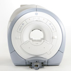
From GE Healthcare;
The GE Signa HDx MRI system is a whole body magnetic resonance scanner designed to support high resolution, high signal to noise ratio, and short scan times.
The 1.5T Signa HDx MR Systems is a modification of the currently marketed GE 1.5T machines, with the main difference being the change to the receive chain architecture that includes a thirty two independent receive channels, and allows for future expansion in 16 channel increments. The overall system has been improved with a simplified user interface
and a single 23" liquid crystal display, improved multi channel surface coil connectivity, and an improved image reconstruction architecture known as the Volume Recon Engine (VRE).
Device Information and Specification CLINICAL APPLICATION Whole body CONFIGURATION Compact short bore Standard: SE, IR, 2D/3D GRE and SPGR, Angiography: 2D/3D TOF, 2D/3D Phase Contrast; 2D/3D FSE, 2D/3D FGRE and FSPGR, SSFP, FLAIR, EPI, optional: 2D/3D Fiesta, FGRET, Spiral, Tensor, 2D 0.7 mm to 20 mm; 3D 0.1 mm to 5 mm 128x512 steps 32 phase encode POWER REQUIREMENTS 480 or 380/415 less than 0.03 L/hr liquid helium | | | | | |
| | | | |
| | | |
|
| |
 | Look
Ups |
| |


