 | Info
Sheets |
| | | | | | | | | | | | | | | | | | | | | | | | |
 | Out-
side |
| | | | |
|
| | | | | |  | Searchterm 'Power' was also found in the following services: | | | | |
|  |  |
| |
|
| | | | | | | | | | |  Further Reading: Further Reading: | | Basics:
|
|
News & More:
| |
| |
| | | | | |
| |
|
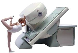
From Esaote S.p.A.;
Esaote introduced the new G-SCAN at the RSNA in Dec. 2004. The G-SCAN covers almost all musculoskeletal applications including the spine. The tilting gantry is designed for scanning in weight-bearing positions. This unique MRI scanner is developed in line with the Esaote philosophy of creating high quality MRI systems that are easy to install and that have a low breakeven point.
Device Information and Specification
SE, GE, IR, STIR, TSE, 3D CE, GE-STIR, 3D GE, ME, TME, HSE
100 up to 350 mm, 25 mm displayed
POWER REQUIREMENTS
100/110/200/220/230/240 V
| | | |
• View the DATABASE results for 'G-SCAN' (3).
| | | | |
| | | | | |
| |
|
| | | | | | | | |
• View the DATABASE results for 'Hardware' (19).
| | |
• View the NEWS results for 'Hardware' (1).
| | | | | | Further Reading: | Basics:
|
|
News & More:
| |
| |
| | | Searchterm 'Power' was also found in the following services: | | | | |
| | |
| |
|
The principal advantage of MRI at high field is the increase in signal to noise ratio. This can be used to improve anatomic and/or temporal resolution and reduce scan time while preserving image quality. MRI devices for whole body imaging for human use are available up to 3 tesla (3T). Functional MRI ( fMRI) and MR spectroscopy ( MRS) benefit significantly. In addition, 3T machines have a great utility in applications such as TOF MRA and DTI. Higher field strengths are used for imaging of small parts of the body or scientific animal experiments. Higher contrast may permit reduction of gadolinium doses and, in some cases, earlier detection of disease.
Using high field MRI//MRS, the RF-wavelength and the dimension of the human body complicating the development of MR coils. The absorption of RF power causes heating of the tissue. The energy deposited in the patient's tissues is fourfold higher at 3T than at 1.5T. The specific absorption rate (SAR) induced temperature changes of the human body are the most important safety issue of high field MRI//MRS.
Susceptibility and chemical shift dispersion increase like T1, therefore high field MRI occasionally exhibits imaging artifacts. Most are obvious and easily recognized but some are subtle and mimic diseases. A thorough understanding of these artifacts is important to avoid potential pitfalls. Some imaging techniques or procedures can be utilized to remove or identify artifacts. See also Diffusion Tensor Imaging.
See also the related poll result: ' In 2010 your scanner will probably work with a field strength of' | | | | | |
• View the DATABASE results for 'High Field MRI' (16).
| | |
• View the NEWS results for 'High Field MRI' (9).
| | | | | | Further Reading: | Basics:
|
|
News & More:
| |
| |
| | | | | |
| |
|
From Philips Medical Systems;
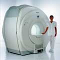
Philips Infinion 1.5 T is designed to maximize the efficiency and quality of patient care. Developed with the patient in mind, the Infinion is the shortest and most open 1.5T scanner available. The unique 'ultra short' 1.4 m magnet assures patient comfort and acceptance without compromising image quality and clinical performance.
Device Information and Specification
CLINICAL APPLICATION
Whole body
CONFIGURATION
Ultra short bore
Head, head / neck, integrated C-spine, L/T spine array, small large GP coils, body flex array, torso pelvis array, breast array, endocavitary, shoulder array, lower extremity, hand / wrist, cardiac, PV array
SE, TSE, SS TSE, EPI, IR, STIR, FLAIR, FFE, TFE, T1 TFE, T2 TFE, Presat, Fatsat, MTC, Diff-opt., Angiography: PCA, MCA, TOF
IMAGING MODES
Single slice, single volume, multi slice, multi volume
80 images/sec std.; up to320 opt.@256
H*W*D
233 (lead fitted) x 198 x 140 cm
POWER REQUIREMENTS
400/480 V
COOLING SYSTEM TYPE
Closed loop, chilled water
| | | |
• View the DATABASE results for 'Infinion 1.5T™' (2).
| | | | |
| | | | |
| | | |
|
| |
 | Look
Ups |
| |


