 | Info
Sheets |
| | | | | | | | | | | | | | | | | | | | | | | | |
 | Out-
side |
| | | | |
|
| | | | |
Result : Searchterm 'Slice Thickness' found in 1 term [ ] and 63 definitions [ ] and 63 definitions [ ] ]
| | previous 56 - 60 (of 64) nextResult Pages : [1] [2 3 4 5 6 7 8 9 10 11 12 13] |  | |  | Searchterm 'Slice Thickness' was also found in the following services: | | | | |
| |  |
| |
|
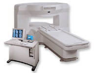
From GE Healthcare;
the New Signa Profile/i is a patient friendly open MRI system that virtually eliminates patient anxiety and claustrophobia, without compromising diagnostic utility.
Device Information and Specification CLINICAL APPLICATION Whole body Integrated transmit body coil, body flex sizes: M, L, XL, quadrature, head coil quadrature, 4 channel neurovascular array, 8 channel CTL array, quad. c- spine, 2 channel shoulder array, extremity coil, 3 channel wrist array, 4 channel breast array, 6, 9, 11 inch general purpose loop coils Standard: SE, IR, 2D/3D GRE and SPGR, Angiography: 2D/3D TOF, 2D/3D phase contrast; 2D/3D FSE, 2D/3D FRFSE, FGRE and FSPGR, SSFP, FLAIR, EPI, optional: 2D/3D Fiesta, fat/water separation, T1 FLAIRIMAGING MODES Localizer, single slice, multislice, volume, fast, POMP, multi slab, cine, slice and frequency zip, extended dynamic range, tailored RF TR 6 to 12000 msec in increments of 1 msec TE 1.3 to 2000 msec in increments of 1 msec 2D: 2.7mm - 20mm 3D: 0.2mm - 5mm 0.08 mm; 0.02 mm optional 10,000 kg w/gradient enclosure POWER REQUIREMENTS 200 - 480, 3-phase COOLING SYSTEM TYPE None required | | | | | |
| | | Searchterm 'Slice Thickness' was also found in the following service: | | | | |
| | |
| |
|
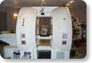
From GE Healthcare;
The Signa SP 0.5T™ is an open MRI magnet that is designed for use in interventional radiology and intra-operative imaging. The vertical gap configuration increases patient positioning options, improves patient observation, and allows continuous access to the patient during imaging.
The magnet enclosure also incorporates an intercom, patient observation video camera, laser patient alignment lights, and task lighting in the imaging volume.
Device Information and Specification CLINICAL APPLICATION Whole body Integrated transmit and receive body coil; optional rotational body coil, head; other coils optional; open architecture makes system compatible with a wide selection of coilsarray Standard: SE, IR, 2D/3D GRE and SPGR, 2D/3D TOF, 2D/3D FSE, 2D/3D FGRE and FSPGR, SSFP, FLAIR, EPI, optional: 2D/3D Fiesta, true chem sat, fat/water separation, single shot diffusion EPI IMAGING MODES Localizer, single slice, multislice, volume, fast, POMP, multi slab, cine, slice and frequency zip, extended dynamic range, tailored RF TR 1.3 to 12000 msec in increments of 1 msec TE 0.4 to 2000 msec in increments of 1 msec 2D: 1.4mm - 20mm 3D: 0.2mm - 20mm POWER REQUIREMENTS 200 - 480, 3-phase | | | |
• View the DATABASE results for 'Signa SP 0.5T™ Open Configuration' (2).
| | | | |  Further Reading: Further Reading: | News & More:
|
|
| |
| | | | | |
| |
|
( SNR or S/N) The signal to noise ratio is used in MRI to describe the relative contributions to a detected signal of the true signal and random superimposed signals ('background noise') - a criterion for image quality.
One common method to increase the SNR is to average several measurements of the signal, on the expectation that random contributions will tend to cancel out. The SNR can also be improved by sampling larger volumes (increasing the field of view and slice thickness with a corresponding loss of spatial resolution) or, within limits, by increasing the strength of the magnetic field used. Surface coils can also be used to improve local signal intensity. The SNR will depend, in part, on the electrical properties of the sample or patient being studied.
The SNR increases in proportion to voxel volume (1/resolution), the square root of the number of acquisitions ( NEX), and the square root of the number of scans ( phase encodings). SNR decreases with the field of view squared (FOV2) and wider bandwidths. See also Signal Intensity and Spin Density.
Measuring SNR:
Record the mean value of a small ROI placed in the most homogeneous area of tissue with high signal intensity (e.g. white matter in thalamus). Calculate the standard deviation for the largest possible ROI placed outside the object in the image background (avoid ghosting/aliasing or eye movement artifact regions).
The SNR is then:
Mean Signal/Standard Deviation of Background Noise | | | | | |
• View the DATABASE results for 'Signal to Noise Ratio' (48).
| | |
• View the NEWS results for 'Signal to Noise Ratio' (2).
| | | | | | Further Reading: | | Basics:
|
|
News & More:
| |
| |
| | | Searchterm 'Slice Thickness' was also found in the following services: | | | | |
| | |
| |
|
The spatial distribution of sensitivity of the imaging process in the direction perpendicular to the plane of the slice. When the profile deviates appreciably from rectangular, the slice thickness alone may not provide an adequate description. | | | |
• View the DATABASE results for 'Slice Profile' (5).
| | | | |
| | | Searchterm 'Slice Thickness' was also found in the following service: | | | | |
| | |
| |
|
Magnetic resonance imaging ( MRI) of the spine is a noninvasive procedure to evaluate different types of tissue, including the spinal cord, vertebral disks and spaces between the vertebrae through which the nerves travel, as well as distinguish healthy tissue from diseased tissue.
The cervical, thoracic and lumbar spine MRI should be scanned in individual sections.
The scan protocol parameter like e.g. the field of view ( FOV), slice thickness and matrix are usually different for cervical, thoracic and lumbar spine MRI, but the method
is similar. The standard views in the basic spinal MRI scan to create detailed slices (cross sections) are sagittal T1 weighted and T2 weighted images over the whole body part, and transverse (e.g. multi angle oblique) over the region of interest with different pulse sequences according to the result of the sagittal slices. Additional views or different types of pulse sequences like fat suppression, fluid attenuation inversion recovery ( FLAIR) or
diffusion weighted imaging are created dependent on the indication.
Indications:
•
Neurological deficit, evidence of radiculopathy, cauda equina compression
•
Primary tumors or drop metastases
•
Infection/inflammatory disease, multiple sclerosis
•
Postoperative evaluation of lumbar spine: disk vs. scar
•
Localized back pain with no radiculopathy (leg pain)
Contrast enhanced MRI techniques delineate infections vs. malignancies, show a syrinx cavity and support to differentiate the postoperative conditions. After surgery for disk disease, significant fibrosis can occur in the spine. This scarring can mimic residual disk herniation. Magnetic resonance myelography evaluates spinal stenosis and various intervertebral discs can be imaged with multi angle oblique techniques. Cine series can be used to show true range of motion studies of parts of the spine.
Advanced open MRI devices are developed to perform positional scans in the position of pain or symptom (e.g. Upright™ MRI formerly Stand-Up MRI). | | | | | |
• View the DATABASE results for 'Spine MRI' (11).
| | |
• View the NEWS results for 'Spine MRI' (4).
| | | | | | Further Reading: | | Basics:
|
|
News & More:
| |
| |
| | | | |
| | | |
|
| |
 | Look
Ups |
| |


