 | Info
Sheets |
| | | | | | | | | | | | | | | | | | | | | | | | |
 | Out-
side |
| | | | |
|
| | | | | |  | Searchterm 'Range' was also found in the following services: | | | | |
|  |  |
| |
|
From
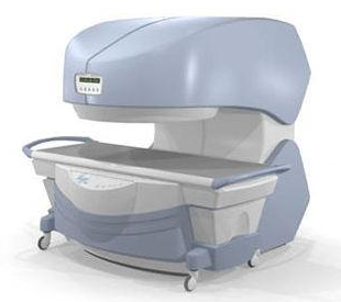
Millennium Technology Inc.
This open C-shaped MRI system eases patient comfort and technologist maneuverability. This low cost scanner is build for a wide range of applications. The Virgo™ patient table is detachable and moves on easy rolling castors. Able to accommodate patient weights up to 160 kg, the tabletop has a range of motion of 30 cm in the lateral direction and 90cm in the longitudinal direction. Images generated with this scanner can only be viewed (without data loss) on Millennium's proprietary viewing software.
Device Information and Specification CLINICAL APPLICATION Whole body Head, Body, Neck, Knee, Shoulder,
Spine, Wrist, Breast, Extremity, Lumbar Spine, TMJ
IMAGING MODES Localizer, single slice, multislice, volume, fast, POMP, multi slab, cine, slice and frequency zip, extended dynamic range, tailored RF | | | | | |
| | | | | |
| |
|
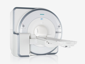
FDA cleared and CE Mark 2011.
The Biograph mMR has a fully-integrated design for simultaneous PET/MRI imaging. The dedicated hardware includes solid-state, avalanche photodiode PET detector and adapted, PET-compatible MR coils.
The possibility of truly simultaneous operation allows the acquisition of several magnetic resonance imaging ( MRI) sequences during the positron emission tomography (PET) scan, without increasing the examination time.
See also Hybrid Imaging.
Device Information and Specification
CLINICAL APPLICATION
Whole Body
CONFIGURATION
Simultaneous PET/MRI
26 cm (typical overlap 23%)
A-P 45, R-L 50, H-F 50 cm
PET RING DIAMETER
65.6 cm
PATIENT SCAN RANGE
199 cm
HORIZONTAL SPEED
200 mmsec
PET DETECTOR
Solid state, 4032 avalanche photo diodes
DETECTOR SCINTILLATION MATERIAL
LSO, 28672 crystals
CRYSTAL SIZE
4 x 4 x 20 mm
DIMENSION H*W*D (gantry included)
335 x 230 x 242 cm (finshed covers)
COOLING SYSTEM
PET system: water; MRI system: water
Aautomatic, patient specific shim; active shim 3 linear and 5 non-linear channels (seond order)
POWER REQUIREMENTS
380 / 400 / 420 / 440 / 460 / 480 V, 3-phase + ground; Total system 110kW
| | | | | |  Further Reading: Further Reading: | | Basics:
|
|
News & More:
| |
| |
| | | | | |
| |
|
Magnetic resonance imaging ( MRI) is based on the magnetic resonance phenomenon, and is used for medical diagnostic imaging since ca. 1977 (see also MRI History).
The first developed MRI devices were constructed as long narrow tunnels. In the meantime the magnets became shorter and wider. In addition to this short bore magnet design, open MRI machines were created. MRI machines with open design have commonly either horizontal or vertical opposite installed magnets and obtain more space and air around the patient during the MRI test.
The basic hardware components of all MRI systems are the magnet, producing a stable and very intense magnetic field, the gradient coils, creating a variable field and radio frequency (RF) coils which are used to transmit energy and to encode spatial positioning. A computer controls the MRI scanning operation and processes the information.
The range of used field strengths for medical imaging is from 0.15 to 3 T. The open MRI magnets have usually field strength in the range 0.2 Tesla to 0.35 Tesla. The higher field MRI devices are commonly solenoid with short bore superconducting magnets, which provide homogeneous fields of high stability.
There are this different types of magnets:
The majority of superconductive magnets are based on niobium-titanium (NbTi) alloys, which are very reliable and require extremely uniform fields and extreme stability over time, but require a liquid helium cryogenic system to keep the conductors at approximately 4.2 Kelvin (-268.8° Celsius). To maintain this temperature the magnet is enclosed and cooled by a cryogen containing liquid helium (sometimes also nitrogen).
The gradient coils are required to produce a linear variation in field along one direction, and to have high efficiency, low inductance and low resistance, in order to minimize the current requirements and heat deposition. A Maxwell coil usually produces linear variation in field along the z-axis; in the other two axes it is best done using a saddle coil, such as the Golay coil.
The radio frequency coils used to excite the nuclei fall into two main categories; surface coils and volume coils.
The essential element for spatial encoding, the gradient coil sub-system of the MRI scanner is responsible for the encoding of specialized contrast such as flow information, diffusion information, and modulation of magnetization for spatial tagging.
An analog to digital converter turns the nuclear magnetic resonance signal to a digital signal. The digital signal is then sent to an image processor for Fourier transformation and the image of the MRI scan is displayed on a monitor.
For Ultrasound Imaging (USI) see Ultrasound Machine at Medical-Ultrasound-Imaging.com.
See also the related poll results: ' In 2010 your scanner will probably work with a field strength of' and ' Most outages of your scanning system are caused by failure of' | | | | | | | | |
• View the DATABASE results for 'Device' (141).
| | |
• View the NEWS results for 'Device' (29).
| | | | | | Further Reading: | News & More:
|
 |
small-steps-can-yield-big-energy-savings-and-cut-emissions-mris
Thursday, 27 April 2023 by www.itnonline.com | | |
Portable MRI can detect brain abnormalities at bedside
Tuesday, 8 September 2020 by news.yale.edu | | |
Point-of-Care MRI Secures FDA 510(k) Clearance
Thursday, 30 April 2020 by www.diagnosticimaging.com | | |
World's First Portable MRI Cleared by FDA
Monday, 17 February 2020 by www.medgadget.com | | |
Low Power MRI Helps Image Lungs, Brings Costs Down
Thursday, 10 October 2019 by www.medgadget.com | | |
Cheap, portable scanners could transform brain imaging. But how will scientists deliver the data?
Tuesday, 16 April 2019 by www.sciencemag.org | | |
The world's strongest MRI machines are pushing human imaging to new limits
Wednesday, 31 October 2018 by www.nature.com | | |
Kyoto University and Canon reduce cost of MRI scanner to one tenth
Monday, 11 January 2016 by www.electronicsweekly.com | | |
A transportable MRI machine to speed up the diagnosis and treatment of stroke patients
Wednesday, 22 April 2015 by medicalxpress.com | | |
Portable 'battlefield MRI' comes out of the lab
Thursday, 30 April 2015 by physicsworld.com | | |
Chemists develop MRI technique for peeking inside battery-like devices
Friday, 1 August 2014 by www.eurekalert.org | | |
New devices doubles down to detect and map brain signals
Monday, 23 July 2012 by scienceblog.com |
|
| |
| | | Searchterm 'Range' was also found in the following services: | | | | |
| | |
| |
|
| | | |
• View the DATABASE results for 'Nuclear Magnetic Resonance Signal' (2).
| | | | | | Further Reading: | | Basics:
|
|
News & More:
| |
| |
| | | | | |
| |
|
Every tissue in the human body has its own T1 and T2 value. This term is used to indicate an image where most of the contrast between tissues is due to differences in the T1 value.
This term may be misleading in that the potentially important effects of tissue density differences and the range of tissue T1 values are ignored.
If the machine parameters are chosen, so that TR less than T1 (typically under 500 ms) and TE less than T2 (typically under 30 ms), a power series expansion of the exponential functions and then neglecting second and higher order terms yields
Mxy = Mxy0 TR/T1
thus the expression becomes independent of T2 and yields the condition for T1 weighting.
Therefore a T1 contrast is approached by imaging with a short TR, compared to the longest tissue T1 of interest and short TE, compared to tissue T2 (to reduce T2 contributions to image contrast). Due to the wide range of T1 and T2 and tissue density values that can be found in the body, an image that is T1 weighted for some tissues may not be so for others.
Lesions with short T1 are (bright in T1 weighted sequences):
fat (lipoma, dermoid)
sub-acute haemorrhage (metHb)
paramagnetic agent (Gd, pituitary)
protein-containing fluid (colloid cyst)
metastatic melanoma (melanotic). | | | | | |
• View the DATABASE results for 'T1 Weighted' (56).
| | | | | | Further Reading: | Basics:
|
|
News & More:
| |
| |
| | | | |
| | | |
|
| |
 | Look
Ups |
| |


