 | Info
Sheets |
| | | | | | | | | | | | | | | | | | | | | | | | |
 | Out-
side |
| | | | |
|
| | | | |
Result : Searchterm 'Transmit Receive Coil' found in 1 term [ ] and 3 definitions [ ] and 3 definitions [ ], (+ 15 Boolean[ ], (+ 15 Boolean[ ] results ] results
| | 1 - 5 (of 19) nextResult Pages : [1] [2 3 4] |  | | | | |  |
| Transmit Receive Coil |   |
| |
|
(T/R) Also called transceiver coil. An RF coil that acts as a transmitter (T) producing the B1 excitation field and as a receiver (R) of the MRI signal. Such a coil requires a T/R switching circuit to switch between the two modes. A body coil is typically a T/R coil, but smaller volume T/R coils (head/extremities) are often used at high field as a possibility of reducing RF power absorption (SAR). | | | | | | | | • Share the entry 'Transmit Receive Coil':    | | | | | | | | | |  Further Reading: Further Reading: | Basics:
|
|
| |
| | | | |  |
| |
|
A RF coil, often a transmit receive coil with a number of wires running along the z-direction, arranged to give a cosine current variation around the circumference of the coil, which looks like a bird cage.
The bird cage coil works on a different principle to conventionally tuned local and surround coils in that it behaves like a tuned transmission line with one complete cycle of standing wave around the circumference. The frequency supply is generated by an oscillator, which is modulated to form a shaped pulse by a product detector controlled by the waveform generator. The signal must be amplified to 1000's of watts. This can be done using either solid state electronics, valves or a combination of both.
The bird cage coil design provides the best field homogeneity of all RF imaging coils.
One advantage is that it is simple to produce an exceedingly uniform B1 radio frequency field over most of the coil's volume, with the result of images with a high degree of uniformity.
A second advantage is that nodes with zero voltage occur 90° away from the driven part of the coil, thus facilitating the introduction of a second signal in quadrature, which produces a circularly polarized radio frequency field.
This type of volume coil is used for brain (head) MRI, or MR imaging of joints, such as the wrist or knees.
See also the related poll result: ' 3rd party coils are better than the original manufacturer coils' | | | | | |
• View the DATABASE results for 'Bird Cage Coil' (4).
| | | | | | Further Reading: | | Basics:
|
|
News & More:
| |
| |
| | | | | |
| |
|
A pacemaker is a device for internal or external battery-operated cardiac pacing to overcome cardiac arrhythmias or heart block. All implanted electronic devices are susceptible to the electromagnetic fields used in magnetic resonance imaging. Therefore, the main magnetic field, the gradient field, and the radio frequency (RF) field are potential hazards for cardiac pacemaker patients.
The pacemaker's susceptibility to static field and its critical role in life support have warranted special consideration. The static magnetic field applies force to magnetic materials. This force and torque effects rise linearly with the field strength of the MRI machines. Both, RF fields and pulsed gradients can induce voltages in circuits or on the pacing lead, which will heat up the tissue around e.g. the lead tip, with a potential risk of thermal injury.
Regulations for pacemakers provide that they have to switch to the magnet mode in static magnetic fields above 1.0 mT. In MR imaging, the gradient and RF fields may mimic signals from the heart with inhibition or fast pacing of the heart. In the magnet mode, most of the current pacemakers will pace with a fix pulse rate because they do not accept the heartsignals. However, the state of an implanted pacemaker will be unpredictable inside a strong magnetic field. Transcutaneous controller adjustment of pacing rate is a feature of many units. Some achieve this control using switches activated by the external application of a magnet to open/close the switch. Others use rotation of an external magnet to turn internal controls. The fringe field around the MRI magnet can activate such switches or controls. Such activations are a safety risk.
Areas with fields higher than 0.5 mT ( 5 Gauss Limit) commonly have restricted access and/or are posted as a safety risk to persons with pacemakers.

A Cardiac pacemaker is because the risks, under normal circumstances an absolute contraindication for MRI procedures.
Nevertheless, with special precaution the risks can be lowered. Reprogramming the pacemaker to an asynchronous mode with fix pacing rate or turning off will reduce the risk of fast pacing or inhibition. Reducing the SAR value reduces the potential MRI risks of heating. For MRI scans of the head and the lower extremities, tissue heating also seems to be a smaller problem. If a transmit receive coil is used to scan the head or the feet, the cardiac pacemaker is outside the sending coil and possible heating is very limited. | | | |
• View the DATABASE results for 'Cardiac Pacemaker' (6).
| | | | | | Further Reading: | Basics:
|
|
News & More:
| |
| |
| | | | | |
| |
|
A coil is a large inductor with a considerable dimension and a defined wavelength, commonly used in configurations for MR imaging. The frequency of the radio frequency coil is defined by the Larmor relationship. The MRI image quality depends on the signal to noise ratio (SNR) of the acquired signal from the patient. Several MR imaging coils are necessary to handle the diversity of applications. Large coils have a large measurement field, but low signal intensity and vice versa (see also coil diameter). The closer the coil to the object, the stronger the signal - the smaller the volume, the higher the SNR. SNR is very important in obtaining clear images of the human body. The shape of the coil depends on the image sampling. The best available homogeneity can be reached by choice of the appropriate coil type and correct coil positioning. Orientation is critical to the sensitivity of the RF coil and therefore the coil should be perpendicular to the static magnetic field.
RF coils can be differentiated by there function into three general categories:
The RF signal is in the range of 10 to 100 MHz. During a typical set of clinical image measurements, the entire frequency spectrum of interest is of the order 10 kHz, which is an extremely narrow band, considering that the center frequency is about 100 MHz. This allows the use of single-frequency matching techniques for coils because their inherent bandwidth always exceeds the image bandwidth. The multi turn solenoid, bird cage coil, single turn solenoid, and saddle coil are typically operated as the transmitter and receiver of RF energy. The surface and phased array coils are typically operated as a receive only coil.
See also the related poll result: ' 3rd party coils are better than the original manufacturer coils' | | | | | |
• View the DATABASE results for 'Radio Frequency Coil' (9).
| | | | | | Further Reading: | Basics:
|
|
News & More:
| |
| |
| | | | |  |
| |
|
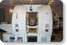
From GE Healthcare;
The Signa SP 0.5T™ is an open MRI magnet that is designed for use in interventional radiology and intra-operative imaging. The vertical gap configuration increases patient positioning options, improves patient observation, and allows continuous access to the patient during imaging.
The magnet enclosure also incorporates an intercom, patient observation video camera, laser patient alignment lights, and task lighting in the imaging volume.
Device Information and Specification CLINICAL APPLICATION Whole body Integrated transmit and receive body coil; optional rotational body coil, head; other coils optional; open architecture makes system compatible with a wide selection of coilsarray Standard: SE, IR, 2D/3D GRE and SPGR, 2D/3D TOF, 2D/3D FSE, 2D/3D FGRE and FSPGR, SSFP, FLAIR, EPI, optional: 2D/3D Fiesta, true chem sat, fat/water separation, single shot diffusion EPI IMAGING MODES Localizer, single slice, multislice, volume, fast, POMP, multi slab, cine, slice and frequency zip, extended dynamic range, tailored RF TR 1.3 to 12000 msec in increments of 1 msec TE 0.4 to 2000 msec in increments of 1 msec 2D: 1.4mm - 20mm 3D: 0.2mm - 20mm POWER REQUIREMENTS 200 - 480, 3-phase | | | |
• View the DATABASE results for 'Signa SP 0.5T™ Open Configuration' (2).
| | | | | | Further Reading: | News & More:
|
|
| |
| | | | |
| | | 1 - 5 (of 19) nextResult Pages : [1] [2 3 4] |
| |
|
| |
 | Look
Ups |
| |


