Magnetic Resonance - Technology Information Portal Welcome to MRI Technology
Info
  Sheets

Out-
      side


 'Pulsed Gradients' 
SEARCH FOR    
 
  2 3 5 A B C D E F G H I J K L M N O P Q R S T U V W X Y Z
Result : Searchterm 'Pulsed Gradients' found in 1 term [] and 1 definition [], (+ 5 Boolean[] results
1 - 5 (of 7)     next
Result Pages : [1]  [2]
Searchterm 'Pulsed Gradients' was also found in the following service: 
spacer
News  (1)  
 
Pulsed Gradients
 
Briefly applied magnetic field gradients.

See also Bipolar Gradient Pulse and Gradient Magnetic Field.
spacer
 
• Share the entry 'Pulsed Gradients':  Facebook  Twitter  LinkedIn  
MRI Resources 
Musculoskeletal and Joint MRI - Process Analysis - Movies - Blood Flow Imaging - Libraries - Services and Supplies
 
Cardiac PacemakerMRI Resource Directory:
 - Safety -
 
A pacemaker is a device for internal or external battery-operated cardiac pacing to overcome cardiac arrhythmias or heart block. All implanted electronic devices are susceptible to the electromagnetic fields used in magnetic resonance imaging. Therefore, the main magnetic field, the gradient field, and the radio frequency (RF) field are potential hazards for cardiac pacemaker patients.
The pacemaker's susceptibility to static field and its critical role in life support have warranted special consideration. The static magnetic field applies force to magnetic materials. This force and torque effects rise linearly with the field strength of the MRI machines. Both, RF fields and pulsed gradients can induce voltages in circuits or on the pacing lead, which will heat up the tissue around e.g. the lead tip, with a potential risk of thermal injury.
Regulations for pacemakers provide that they have to switch to the magnet mode in static magnetic fields above 1.0 mT. In MR imaging, the gradient and RF fields may mimic signals from the heart with inhibition or fast pacing of the heart. In the magnet mode, most of the current pacemakers will pace with a fix pulse rate because they do not accept the heartsignals. However, the state of an implanted pacemaker will be unpredictable inside a strong magnetic field. Transcutaneous controller adjustment of pacing rate is a feature of many units. Some achieve this control using switches activated by the external application of a magnet to open/close the switch. Others use rotation of an external magnet to turn internal controls. The fringe field around the MRI magnet can activate such switches or controls. Such activations are a safety risk.
Areas with fields higher than 0.5 mT (5 Gauss Limit) commonly have restricted access and/or are posted as a safety risk to persons with pacemakers.
mri safety guidance
MRI Safety Guidance
A Cardiac pacemaker is because the risks, under normal circumstances an absolute contraindication for MRI procedures.
Nevertheless, with special precaution the risks can be lowered. Reprogramming the pacemaker to an asynchronous mode with fix pacing rate or turning off will reduce the risk of fast pacing or inhibition. Reducing the SAR value reduces the potential MRI risks of heating. For MRI scans of the head and the lower extremities, tissue heating also seems to be a smaller problem. If a transmit receive coil is used to scan the head or the feet, the cardiac pacemaker is outside the sending coil and possible heating is very limited.
spacer

• View the DATABASE results for 'Cardiac Pacemaker' (6).Open this link in a new window

 
Further Reading:
  Basics:
MRI in Patients with Implanted Devices: Current Controversies
Monday, 1 August 2016   by www.acc.org    
Magnetic resonance imaging in patients with cardiac pacemakers: era of MR Conditional designs
Thursday, 27 October 2011   by 7thspace.com    
  News & More:
Newer Heart Devices Safe During MRI
Monday, 23 August 2004   by www.hospimedica.com    
BIOTRONIK debuts pacemaker with continuous MRI sensor
Wednesday, 30 August 2023   by www.medicaldevice-network.com    
Patients with standard pacemakers, ICDs may safely undergo MRIs
Friday, 24 February 2017   by www.cardiovascularbusiness.com    
ITOCHU Named the Exclusive Distributor for ViewRay's MRI-Guided Radiation Therapy System in Japan
Thursday, 22 January 2015   by www.prnewswire.com    
Modern Implantable Heart Devices Safe For Use In MRI Scans
Wednesday, 16 March 2005   by www.sciencedaily.com    
MRI Resources 
Shoulder MRI - Stent - Bioinformatics - Nerve Stimulator - Pediatric and Fetal MRI - Mobile MRI
 
Gradient Echo SequenceForum -
related threadsInfoSheet: - Sequences - 
Intro, 
Overview, 
Types of, 
etc.
 
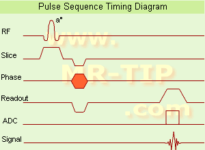
Gradient Echo Sequence Timing Diagram (GRE - sequence) A gradient echo is generated by using a pair of bipolar gradient pulses. In the pulse sequence timing diagram, the basic gradient echo sequence is illustrated. There is no refocusing 180° pulse and the data are sampled during a gradient echo, which is achieved by dephasing the spins with a negatively pulsed gradient before they are rephased by an opposite gradient with opposite polarity to generate the echo.
See also the Pulse Sequence Timing Diagram. There you will find a description of the components.
The excitation pulse is termed the alpha pulse α. It tilts the magnetization by a flip angle α, which is typically between 0° and 90°. With a small flip angle there is a reduction in the value of transverse magnetization that will affect subsequent RF pulses. The flip angle can also be slowly increased during data acquisition (variable flip angle: tilt optimized nonsaturation excitation). The data are not acquired in a steady state, where z-magnetization recovery and destruction by ad-pulses are balanced. However, the z-magnetization is used up by tilting a little more of the remaining z-magnetization into the xy-plane for each acquired imaging line.
Gradient echo imaging is typically accomplished by examining the FID, whereas the read gradient is turned on for localization of the signal in the readout direction. T2* is the characteristic decay time constant associated with the FID. The contrast and signal generated by a gradient echo depend on the size of the longitudinal magnetization and the flip angle. When α = 90° the sequence is identical to the so-called partial saturation or saturation recovery pulse sequence. In standard GRE imaging, this basic pulse sequence is repeated as many times as image lines have to be acquired. Additional gradients or radio frequency pulses are introduced with the aim to spoil to refocus the xy-magnetization at the moment when the spin system is subject to the next α pulse.
As a result of the short repetition time, the z-magnetization cannot fully recover and after a few initial α pulses there is an equilibrium established between z-magnetization recovery and z-magnetization reduction due to the α pulses.
Gradient echoes have a lower SAR, are more sensitive to field inhomogeneities and have a reduced crosstalk, so that a small or no slice gap can be used. In or out of phase imaging depending on the selected TE (and field strength of the magnet) is possible. As the flip angle is decreased, T1 weighting can be maintained by reducing the TR. T2* weighting can be minimized by keeping the TE as short as possible, but pure T2 weighting is not possible. By using a reduced flip angle, some of the magnetization value remains longitudinal (less time needed to achieve full recovery) and for a certain T1 and TR, there exist one flip angle that will give the most signal, known as the "Ernst angle".
Contrast values:
PD weighted: Small flip angle (no T1), long TR (no T1) and short TE (no T2*)
T1 weighted: Large flip angle (70°), short TR (less than 50ms) and short TE
T2* weighted: Small flip angle, some longer TR (100 ms) and long TE (20 ms)

Classification of GRE sequences can be made into four categories:
See also Gradient Recalled Echo Sequence, Spoiled Gradient Echo Sequence, Refocused Gradient Echo Sequence, Ultrafast Gradient Echo Sequence.
 
Images, Movies, Sliders:
 MRI Liver In Phase  Open this link in a new window
    
 MRI Liver Out Of Phase  Open this link in a new window
    
 MVP Parasternal  Open this link in a new window
 Breast MRI Images T1 Pre - Post Contrast  Open this link in a new window
 Circle of Willis, Time of Flight, MIP  Open this link in a new window
    
SlidersSliders Overview

 
spacer

• View the DATABASE results for 'Gradient Echo Sequence' (70).Open this link in a new window

 
Further Reading:
  Basics:
Enhanced Fast GRadient Echo 3-Dimensional (efgre3D) or THRIVE
   by www.mri.tju.edu    
  News & More:
MRI evaluation of fatty liver in day to day practice: Quantitative and qualitative methods
Wednesday, 3 September 2014   by www.sciencedirect.com    
T1rho-prepared balanced gradient echo for rapid 3D T1rho MRI
Monday, 1 September 2008   by www.ncbi.nlm.nih.gov    
Searchterm 'Pulsed Gradients' was also found in the following service: 
spacer
News  (1)  
 
Incoherent Gradient Echo (RF Spoiled)InfoSheet: - Sequences - 
Intro, 
Overview, 
Types of, 
etc.
 
A gradient echo is generated by using a pair of bipolar gradient pulses. The gradient field is negatively pulsed, causing the spins of the xy-magnetization to dephase. A second gradient pulse is applied with the opposite polarity. During the pulsing, the spins that dephased begin to rephase and generate a gradient echo.
Spoiling can be accomplished by RF or a gradient. The incoherent RF spoiled type of a gradient echo sequence use a continuous shifting of the RF pulse to spoil the residual transverse magnetization. The phase of the RF excitation and receiver channel are varied pseudo randomly with each excitation cycle to prevent the xy magnetization from achieving steady state. T2* does not dominate image contrast, so T1 and PD weighting is practical. This method is effective and can be used to achieve a shorter TR, due to a lack of additional gradients. Spoiling eliminates the effect of the remaining xy-magnetization and leads to steady state longitudinal magnetization. These sequences can be used for breath hold, dynamic imaging and in cine and volume acquisitions.
spacer
MRI Resources 
Used and Refurbished MRI Equipment - MR Guided Interventions - Universities - Mobile MRI Rental - Brain MRI -
 
Magnetic ForcesMRI Resource Directory:
 - MRI Accidents -
 
Forces can result from the interaction of magnetic fields. Pulsed magnetic field gradients can interact with the main magnetic field during the MRI scan, to produce acoustic noise through the gradient coil.
Magnetic fields attract ferromagnetic objects with forces, which can be a lethal danger if one is hit by an unrestrained object in flight. One could also be trapped between the magnet and a large unrestrained ferromagnetic object or the object could damage the MRI machine.
Access control and personnel awareness are the best preventions of such accidents. The attraction mechanism for ferromagnetic objects is that the magnetic field magnetizes the iron. This induced magnetization reacts with the gradient of the magnetic field to produce an attraction toward the strongest area of the field. The details of this interaction are very dependent on the shape and composition of the attracted object. There is a very rapid increase of force as one approaches a magnet. There is also a torque or twisting force on objects, e.g. a long cylinder (such as a pen or an intracranial aneurysm clip) will tend to align along the magnet's field lines. The torque increases with field strength while the attraction increases with field gradient.
Depending on the magnetic saturation of the object, attraction is roughly proportional to object mass. Motion of conducting objects in magnetic fields can induce eddy currents that can have the effect of opposing the motion.

See also Duty Cycle.

See also the related poll result: 'Most outages of your scanning system are caused by failure of'
spacer

• View the DATABASE results for 'Magnetic Forces' (4).Open this link in a new window

 
Further Reading:
  Basics:
How strong are magnets?
   by my.execpc.com    
Magnetic Field of the Strongest Magnet
2003   by hypertextbook.com    
  News & More:
Imaging chain faces regulators after inmate, guard get stuck to MRI machine
Friday, 1 December 2023   by healthimaging.com    
Measuring magnetic force field distributions in microfluidic devices: Experimental and numerical approaches
Saturday, 2 December 2023   by analyticalsciencejournals.onlinelibrary.wiley.com    
Two stuck to MRI machine for 4 hrs
Tuesday, 11 November 2014   by www.mumbaimirror.com    
New imaging project for new applications in cancer diagnostics
Monday, 27 March 2017   by www.news-medical.net    
MRI Resources 
Safety Training - - Mobile MRI Rental - Implant and Prosthesis pool - Resources - Raman Spectroscopy
 
     1 - 5 (of 7)     next
Result Pages : [1]  [2]
 Random Page
 
Share This Page
FacebookTwitterLinkedIn

MR-TIP    
Community   
User
Pass
Forgot your UserID/Password ?    


How AI will impact MRI :
only diagnostics 
saving time 
reducing cost 
makes planning obsolete 
reduce human knowledge 
not at all 

Look
      Ups


MR-TIP.com uses cookies! By browsing MR-TIP.com, you agree to our use of cookies.

Magnetic Resonance - Technology Information Portal
Member of SoftWays' Medical Imaging Group - MR-TIP • Radiology-TIP • Medical-Ultrasound-Imaging • 
Copyright © 2003 - 2024 SoftWays. All rights reserved. [ 18 April 2024]
Terms of Use | Privacy Policy | Advertising
 [last update: 2024-02-26 03:41:00]