 | Info
Sheets |
| | | | | | | | | | | | | | | | | | | | | | | | |
 | Out-
side |
| | | | |
|
| | | | | |  | Searchterm 'Second' was also found in the following services: | | | | |
|  |  |
| |
|
Producing electricity in a secondary coil or wire by passing an AC current through a nearby primary coil. | | | | | |
| | | Searchterm 'Second' was also found in the following services: | | | | |
| | |
| |
|
Phase differences in every second line produce striped ghosts with a shift of half the field of view, so-called Nyquist ghosts. | | | |
• View the DATABASE results for 'Nyquist Ghost' (2).
| | | | |
| | | | | |
| |
|
If available, some graphic aids can be helpful to show image orientations.
1) A graphic icon of the labeled primary axes (A, L, H) with relative lengths given by direction sines and orientation as if viewed from the normal to the image plane can help orient the viewer, both to identify image plane orientation and to indicate possible in plane rotation.
2) Ingraphic prescription of obliques from other images, a sample original image with an overlaid line or set of lines indicating the intersection of the original and oblique image planes can help orient the viewer.
•
The basic anatomical directions are:
right(R) to left (L), posterior (P) to anterior (A), and feet (F) to head (H).
•
A standard display orientation for images in the basic slice orientation is:
1) transverse: A to top of image and L to right,
2) coronal: H to top of image and L to right and
3) sagittal: H to top of image and A to left.
The location in the R/L and P/A directions can be specified relative to the axis of the magnet.
The F/H location can be specified relative to a convenient patient structure.
The orientation of single oblique slices can be specified by rotating a slice in one of the basic orientations toward one of the other two basic orthogonal planes about an axis defined by the intersection of the 2 planes.
Double oblique slices can be specified as the result of tipping a single oblique plane toward the remaining basic orientation plane, about an axis defined by the intersection of the oblique plane and the remaining basic plane. In double oblique angulations, the first rotation is chosen about the vertical image axis and the second about the (new) horizontal axis.
Angles are chosen to have magnitudes less than 90° (for single oblique slices less than 45°); the sign of the angle is taken to be positive when the rotation brings positive axes closer together. | | | | | |
• View the DATABASE results for 'Orientation' (16).
| | | | |
| | | Searchterm 'Second' was also found in the following services: | | | | |
| | |
| |
|
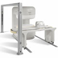
From Philips Medical Systems;
the Panorama 0.23 T, providing a new design optimized for patient comfort, faster reconstruction time than before (300 images/ second) and new gradient
specifications. Philips' Panorama 0.23 T I/T supports MR-guided interventions, resulting in minimally invasive procedures, more targeted surgery, reduced recovery time and shorter hospital stays. Optional OptoGuide functionality enables real-time needle tracking. Philips' Panorama 0.23 TPanorama 0.2 R/T is the first and only open MRI system to enable radiation therapy planning using MR data sets. The Panorama also features the new and consistent Philips User Interface, an essential element of the Vequion clinical IT family of products and services.
Device Information and Specification CLINICAL APPLICATION Whole body SE, FE, IR, FFE, DEFFE, DESE, TSE, DETSE, Single shot SE, DRIVE, Balanced FFE, MRCP, Fluid Attenuated Inversion Recovery, Turbo FLAIR, IR-TSE, T1-STIR TSE, T2-STIR TSE, Diffusion Imaging, 3D SE, 3D FFE, MTC;; Angiography: CE-ANGIO, MRA 2D, 3D TOFOpen x 46 cm x infinite (side-first patient entry) POWER REQUIREMENTS 400/480 V COOLING SYSTEM TYPE Closed loop chilled water ( chiller included) | | | |
• View the DATABASE results for 'Panorama 0.23T™' (2).
| | | | |  Further Reading: Further Reading: | News & More:
|
|
| |
| | | Searchterm 'Second' was also found in the following services: | | | | |
| | |
| |
|
| | | |
• View the DATABASE results for 'Phase Encoding Gradient' (18).
| | | | | | Further Reading: | | Basics:
|
 |
RARE
Monday, 3 December 2012 by www2.warwick.ac.uk |
|
News & More:
| |
| |
| | | | |
| | |
| | | |
|
| |
 | Look
Ups |
| |


