 | Info
Sheets |
| | | | | | | | | | | | | | | | | | | | | | | | |
 | Out-
side |
| | | | |
|
| | | | |
Result : Searchterm 'K-Space' found in 6 terms [ ] and 56 definitions [ ] and 56 definitions [ ] ]
| | previous 21 - 25 (of 62) nextResult Pages : [1 2] [3 4 5 6 7 8 9 10 11 12 13] |  | |  | Searchterm 'K-Space' was also found in the following services: | | | | |
| |  |
| |
|
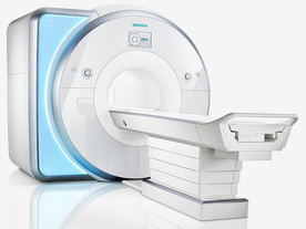
From Siemens Medical Systems;
Received FDA clearance in 2010.
MAGNETOM Skyra is a top-of-the-line, patient friendly wide bore 3 Tesla MRI system.
The system is equipped with the Tim 4G and Dot system (Total imaging matrix and Day optimizing throughput), to enhance both productivity and image quality with the complete range of advanced applications for clinical routine and research. Tim 4G features lighter, trimmer MRI coils that take up less space inside the magnet but deliver a high coil element density with increased signal to noise ratio and the possibility to use high iPAT factors.
Device Information and Specification
CLINICAL APPLICATION
Whole Body
Head, spine, torso/ body coil, neurovascular, cardiac, neck, shoulder, knee, wrist, foot//ankle and multi-purpose flex coils. Peripheral vascular, breast, shoulder.
CHANNELS (min. / max. configuration)
48, 64, 128
Chemical shift imaging, single voxel spectroscopy
MINIMUM TE
3D T1 spoiled GRE: 0.22 (256 matrix), Ultra-short TE
At isocenter: L-R 70 cm, A-P (with table) 55 cm
MAGNET WEIGHT (gantry included)
5768 kg
DIMENSION H*W*D (gantry included)
173 x 231 x 219 cm
COOLING SYSTEM
Water; single cryogen, 2 stage refrigeration
3 linear with 20 coils, 5 nonlinear 2nd-order
POWER REQUIREMENTS
380 / 400 / 420 / 440 / 460 / 480 V, 3-phase + ground; 110 kVA
| | | | | |
| | | | | |
| |
|
When a multi shot technique is applied, each shot will have its own effect on the prepulse, with a scan time increase. Multiple shots allow a shorter IR delay but at the cost of increased scan time.
In multi shot technique (also called mosaic imaging), a group of samples, which are contiguous in k space are acquired in the same sequence repetition. The phase encoding steps or profiles are split into 'shots' (sub-acquisitions). The shot interval is the time between the shots. Usually kept as short as possible. Because the acquisitions are divided into different shots, each shot will have less T1 variation, thereby increasing T1 contrast. Two excitations, each requiring the data for one half of k-space, are the simplest variation of multi shot techniques (e.g. positive versus negative phase encoding).
The alternative to this mosaic strategy for multi shot EPI is interleaving. In interleaved sequences, each repetition acquires every nth (n is the number of shots) line in k-space and for the complete raw data set the various repetition data are interlaced.
See also Single Shot Technique. | | | | | |
| | | | | |
| |
|
In parallel MR imaging, a reduced data set in the phase encoding direction(s) of k-space is acquired to shorten acquisition time, combining the signal of several coil arrays. The spatial information related to the phased array coil elements is utilized for reducing the amount of conventional Fourier encoding.
First, low-resolution, fully Fourier-encoded reference images are required for sensitivity assessment. Parallel imaging reconstruction in the Cartesian case is efficiently performed by creating one aliased image for each array element using discrete Fourier transformation. The next step then is to create an full FOV image from the set of intermediate images.
Parallel reconstruction techniques can be used to improve the image quality with increased signal to noise ratio, spatial resolution, reduced artifacts, and the temporal resolution in dynamic MRI scans.
Parallel imaging algorithms can be divided into 2 main groups:
Image reconstruction produced by each coil ( reconstruction in the image domain, after Fourier transform): SENSE ( Sensitivity Encoding), PILS (Partially Parallel Imaging with Localized Sensitivity),
ASSET.
Reconstruction of the Fourier plane of images from the frequency signals of each coil ( reconstruction in the frequency domain, before Fourier transform): GRAPPA. Additional techniques include SMASH, SPEEDER™,
IPAT (Integrated Parallel Acquisition Techniques - derived of GRAPPA a k-space based technique) and mSENSE (an image based enhanced version of SENSE).
| | | | | |
• View the DATABASE results for 'Parallel Imaging Technique' (12).
| | | | |  Further Reading: Further Reading: | | Basics:
|
|
News & More:
| |
| |
| | | Searchterm 'K-Space' was also found in the following services: | | | | |
| | |
| |
|
| | | |
• View the DATABASE results for 'Partial Echo' (4).
| | | | | | Further Reading: | Basics:
|
|
| |
| | | | | |
| |
|
| | | |
• View the DATABASE results for 'Phase Conjugate Symmetry' (3).
| | | | |
| | | | |
| | |
| | | |
|
| |
 | Look
Ups |
| |


