 | Info
Sheets |
| | | | | | | | | | | | | | | | | | | | | | | | |
 | Out-
side |
| | | | |
|
| | | | |
Result : Searchterm 'Half' found in 5 terms [ ] and 34 definitions [ ] and 34 definitions [ ] ]
| | previous 11 - 15 (of 39) nextResult Pages : [1] [2 3 4 5 6 7 8] |  | |  | Searchterm 'Half' was also found in the following services: | | | | |
| |  |
| |
|
The symmetry in k-space is a fundamental property of Fourier transformations. For a two-dimensional example, let g(x,y) be a complex function, i.e. the value of g at any (x,y) is a complex number. If nothing is known about the function g, data throughout all of k-space is needed to fully characterize it.
If the function g is 'real', meaning that at every (x,y) the imaginary component of g(x,y) is zero, then you only need half as much data to characterize g. The result is redundancy between the data on one half of k-space and the other. Specifically, if G(kx,ky) is the Fourier transformation of g(x,y), and g(x,y) is real, then G(kx,ky)=G*(- kx,- ky), where * indicates a complex conjugate. The data in mirrored positions in k-space, i.e. (kx,ky) versus (- kx,- ky), are conjugates of each other. See Imaginary Numbers and Complex Conjugate. | | | | | |  Further Reading: Further Reading: | Basics:
|
|
| |
| | | | | |
| |
|
Quick Overview Please note that there are different common names for this artifact.
DESCRIPTION
Striped ghosts with a shift of half the field of view
Machine imperfection-based artifacts manifest themselves due to the fact that the odd k-space lines are acquired in a different direction than the even k-space lines. Slight differences in timing result in shifts of the echo in the acquisition window. By the shift theorem, such shifts in the time domain data then produce linear phase differences in the frequency domain data.
Without correction, such phase differences in every second line produce striped ghosts with a shift of half the field of view, so-called Nyquist ghosts. Shifts in the applied magnetic field can also produce similar (but constant in amplitude) ghosts.
This artifact is commonly seen in an EPI image and can arise from both, hardware and sample imperfections.
A further source of machine-based artifact arises from the need to acquire the signal as quickly as possible. For this reason the EPI signal is often acquired during times when the gradients are being switched. Such sampling effectively means that the k-space sampling is not uniform, resulting in ringing artifacts in the image.

Image Guidance
Such artifacts can be minimized by careful setup of the spectrometer and/or correction of the data. For this reasons reference data are often collected, either as a separate scan or embedded in the imaging data.
The non-uniform sampling can be removed by knowing the form of the gradient switching. It is possible to regrid the data onto a uniform k-space grid. | | | |
• View the DATABASE results for 'Machine Imperfection Artifact' (2).
| | | | | | Further Reading: | Basics:
|
|
| |
| | | | | |
| |
|
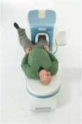
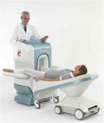
O-scan is manufactured and distributed by Esaote SpA
O-scan is a compact, dedicated extremity MRI system designed for easy installation and high throughput. The complete system fits in a 9' x 10' room, doesn't need for RF or magnetic shielding and it plugs in the wall. The 0.31T permanent magnet along with dual phased array RF coils, and advanced imaging protocols provide outstanding image quality and fast 25 minute complete examinations.
Esaote North America is the exclusive distributor of the O-scan system in the USA.
Device Information and Specification CLINICAL APPLICATION Dedicated Extremity
PULSE SEQUENCES
SE, HSE, HFE, GE, 2dGE, ME, IR, STIR, Stir T2, GESTIR, TSE, TME, FSE STIR, FSE ( T1, T2), X-Bone, Turbo 3DT1, 3D SHARC, 3D SST1, 3D SST2 2D: 2mm - 10 mm, 3D: 0.6 - 10 mm POWER REQUIREMENTS 100/110/200/220/230/240 | | | | | |
| | | Searchterm 'Half' was also found in the following services: | | | | |
| | |
| |
|
If the receiving RF coil is sensitive to tissue signal arising from outside the desired FOV, this undesired signal may be incorrectly mapped to a location within the image, a phenomenon known as aliasing. This is a consequence of the acquired k-space frequencies not being sampled densely enough, whereby portions of the object outside of the desired FOV get mapped to an incorrect location inside the FOV.
The sampling frequency should be at least twice the frequency being sampled. The maximum measurable frequency is therefore equal to half the sampling frequency. This is the so-called Nyquist limit. When the frequency is higher than the Nyquist limit, aliasing occurs.
A similar problem occurs in the phase encoding direction, where the phases of signal-bearing tissues outside of the FOV in the y-direction are a replication of the phases that are encoded within the FOV. This signal will be mapped, or wrapped back into the image at incorrect locations, and is seen as artifact.
See also Aliasing Artifact. | | | |
• View the DATABASE results for 'Aliasing' (19).
| | | | | | Further Reading: | News & More:
|
|
| |
| | | | | |
| |
|
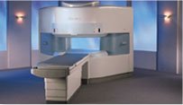
From Hitachi Medical Systems America, Inc.;
the AIRIS made its debut in 1995. Hitachi followed up with the AIRIS II system, which has proven equally successfully. 'All told, Hitachi has installed more than 1,000 MRI systems in the U.S., holding more than 17 percent of the total U.S. MRI installed base, and more than half of the installed base of open MR systems,' says Antonio Garcia, Frost and Sullivan industry research analyst.
Now Altaire employs a blend of innovative Hitachi features called VOSI™ technology, optimizing each sub-system's performance in concert with the
other sub-systems, to give the seamless mix of high-field performance
and the patient comfort, especially for claustrophobic patients, of open MR systems.
Device Information and Specification
CLINICAL APPLICATION
Whole body
DualQuad T/R Body Coil, MA Head, MA C-Spine, MA Shoulder, MA Wrist, MA CTL Spine, MA Knee, MA TMJ, MA Flex Body (3 sizes), Neck, small and large Extremity, PVA (WIP), Breast (WIP), Neurovascular (WIP), Cardiac (WIP) and MA Foot//Ankle (WIP)
SE, GE, GR, IR, FIR, STIR, ss-FSE, FSE, DE-FSE/FIR, FLAIR, ss/ms-EPI, ss/ms EPI- DWI, SSP, MTC, SE/GE-EPI, MRCP, SARGE, RSSG, TRSG, BASG, Angiography: CE, PC, 2D/3D TOF
IMAGING MODES
Single, multislice, volume study
TR
SE: 30 - 10,000msec GE: 3.6 - 10,000msec IR: 50 - 16,700msec FSE: 200 - 16,7000msec
TE
SE : 8 - 250msec IR: 5.2 -7,680msec GE: 1.8 - 2,000 msec FSE: 5.2 - 7,680
0.05 sec/image (256 x 256)
2D: 2 - 100 mm; 3D: 0.5 - 5 mm
Level Range: -2,000 to +4,000
COOLING SYSTEM TYPE
Water-cooled
3.1 m lateral, 3.6 m vertical
| | | |
• View the DATABASE results for 'Altaire™' (2).
| | | | | | Further Reading: | News & More:
|
|
| |
| | | | |
| | |
| | | |
|
| |
 | Look
Ups |
| |


