Magnetic Resonance - Technology Information Portal Welcome to MRI Technology
Info
  Sheets

Out-
      side


 'Distortion' 
SEARCH FOR    
 
  2 3 5 A B C D E F G H I J K L M N O P Q R S T U V W X Y Z
Result : Searchterm 'Distortion' found in 1 term [] and 11 definitions []
previous     6 - 10 (of 12)     next
Result Pages : [1]  [2 3]
Searchterm 'Distortion' was also found in the following services: 
spacer
Forum  (6)  
 
Echo Planar ImagingInfoSheet: - Sequences - 
Intro, 
Overview, 
Types of, 
etc.MRI Resource Directory:
 - Sequences -
 
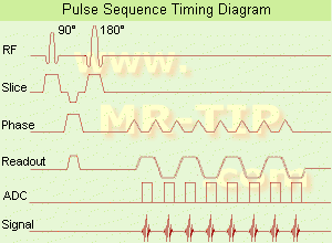
Echo Planar Imaging Timing Diagram (EPI) Echo planar imaging is one of the early magnetic resonance imaging sequences (also known as Intascan), used in applications like diffusion, perfusion, and functional magnetic resonance imaging. Other sequences acquire one k-space line at each phase encoding step. When the echo planar imaging acquisition strategy is used, the complete image is formed from a single data sample (all k-space lines are measured in one repetition time) of a gradient echo or spin echo sequence (see single shot technique) with an acquisition time of about 20 to 100 ms. The pulse sequence timing diagram illustrates an echo planar imaging sequence from spin echo type with eight echo train pulses. (See also Pulse Sequence Timing Diagram, for a description of the components.)
In case of a gradient echo based EPI sequence the initial part is very similar to a standard gradient echo sequence. By periodically fast reversing the readout or frequency encoding gradient, a train of echoes is generated.
EPI requires higher performance from the MRI scanner like much larger gradient amplitudes. The scan time is dependent on the spatial resolution required, the strength of the applied gradient fields and the time the machine needs to ramp the gradients.
In EPI, there is water fat shift in the phase encoding direction due to phase accumulations. To minimize water fat shift (WFS) in the phase direction fat suppression and a wide bandwidth (BW) are selected. On a typical EPI sequence, there is virtually no time at all for the flat top of the gradient waveform. The problem is solved by "ramp sampling" through most of the rise and fall time to improve image resolution.
The benefits of the fast imaging time are not without cost. EPI is relatively demanding on the scanner hardware, in particular on gradient strengths, gradient switching times, and receiver bandwidth. In addition, EPI is extremely sensitive to image artifacts and distortions.
spacer
 
• Related Searches:
    • Echo Planar Imaging Factor
    • Functional Magnetic Resonance Imaging
    • K-Space Trajectory
    • Perfusion Imaging
    • Sensitivity Encoding
 
Further Reading:
  Basics:
New Imaging Method Makes Brain Scans 7 Times Faster
Sunday, 9 January 2011   by www.dailytech.com    
Searchterm 'Distortion' was also found in the following services: 
spacer
Radiology  (2) Open this link in a new windowUltrasound  (4) Open this link in a new window
Eddy Current ArtifactInfoSheet: - Artifacts - 
Case Studies, 
Reduction Index, 
etc.
 
Quick Overview
Artifact Information
NAME
Eddy current
DESCRIPTION
Image distortion
REASON
Induced by changes in a magnetic field
Eddy currents can cause artifacts in images and may seriously degrade overall magnet performance.
mri safety guidance
Image Guidance
Common uses to reduce the influence of eddy currents on gradient fields are eddy current compensation and shielded gradient coils (active or passive). If persistent, it must be addressed by a service representative to verify the magnet performance.

See also Eddy Current Compensation.
spacer

• View the DATABASE results for 'Eddy Current Artifact' (2).Open this link in a new window

 
Further Reading:
  Basics:
Generic Eddy Current Compensation for Rapid Magnetic Resonance Imaging(.pdf)
   by www.switt.ch    
MRI Resources 
Bioinformatics - Mobile MRI - MRI Centers - Absorption and Emission - Examinations - MRI Technician and Technologist Jobs
 
Field Inhomogeneity ArtifactInfoSheet: - Artifacts - 
Case Studies, 
Reduction Index, 
etc.MRI Resource Directory:
 - Artifacts -
 
Quick Overview
Artifact Information
NAME
Field inhomogeneity
DESCRIPTION
Image distortion signal loss
REASON
HELP
Larger FOV, oversampling
A disturbance of the field homogeneity, because of magnetic material (inside or outside the patient), technical problems or scanning at the edge of the field.
When images were obtained in a progression from the center to the edge of the coil, the homogeneity of the field observed by the imaged volume, changes when the distance from the center of the volume increase. The same problem appears by scanning at a distance from the isocenter in left-right direction or too large field of view.
There are different types of bad image quality, the images are noisy, distorted or the fat suppression doesn't work because of badly set shim currents.
E.g. by using an IR sequence, changes in the T1 recovery rates of the tissues are involved. The inversion time at the center of the imaged volume is appropriate to suppress fat, but at the edge of the coil the same inversion time is sufficient to suppress water. Since the inversion time is not changed, the T1 recovery rates will increase.
mri safety guidance
Image Guidance
Take a smaller imaging volume (and for fat suppression a volume shimming), take care that the imaged region is at the center of the coil and that no magnetic material is inside the imaging volume.
spacer

• View the DATABASE results for 'Field Inhomogeneity Artifact' (3).Open this link in a new window

 
Further Reading:
  Basics:
MRI Artifact Gallery
   by chickscope.beckman.uiuc.edu    
Searchterm 'Distortion' was also found in the following services: 
spacer
Forum  (6)  
 
Flat TopForum -
related threads
 
The flat top is the area at the top of the frequency encoding gradient where the data sampling occurs. By increasing the BW the amount of time the flat top is on is reduced. Shortening the duration of the flat top shortens the echo spacing and also geometric distortions. The area under the frequency gradient determines the FOV, while the flat top determines the number of samples to be collected.
spacer

• View the DATABASE results for 'Flat Top' (3).Open this link in a new window

Searchterm 'Distortion' was also found in the following services: 
spacer
Radiology  (2) Open this link in a new windowUltrasound  (4) Open this link in a new window
Gradient Moment Nulling
 
Gradient moment nulling used as motion artifact suppression technique (MAST) reduces constant velocity motion distortion in standard spin echo or gradient echo pulse sequences. It is an adjustment to zero at the echo time (TE) of the net moments of the amplitude of the waveform of the magnetic field gradients with time. The zeroth moment is the area under the curve. The first moment is the 'center of gravity' etc.
The aim is to minimize the phase shifts acquired by the transverse magnetization of excited nuclei moving along the gradients (including the effect of refocusing radio frequency pulses), particularly for the reduction of image artifacts due to motion.
spacer

• View the DATABASE results for 'Gradient Moment Nulling' (7).Open this link in a new window

 
Further Reading:
  Basics:
Motion Compensation in MR Imaging
   by ccn.ucla.edu    
MRI Resources 
Stent - Knee MRI - Sequences - Nerve Stimulator - - Liver Imaging
 
previous      6 - 10 (of 12)     next
Result Pages : [1]  [2 3]
 Random Page
 
Share This Page
FacebookTwitterLinkedIn

MR-TIP    
Community   
User
Pass
Forgot your UserID/Password ?    


How AI will impact MRI :
only diagnostics 
saving time 
reducing cost 
makes planning obsolete 
reduce human knowledge 
not at all 

Look
      Ups


MR-TIP.com uses cookies! By browsing MR-TIP.com, you agree to our use of cookies.

Magnetic Resonance - Technology Information Portal
Member of SoftWays' Medical Imaging Group - MR-TIP • Radiology-TIP • Medical-Ultrasound-Imaging • 
Copyright © 2003 - 2024 SoftWays. All rights reserved. [ 3 May 2024]
Terms of Use | Privacy Policy | Advertising
 [last update: 2024-02-26 03:41:00]