| Info
Sheets |
| | | | | | | | | | | | | | | | | | | | | | | | |
 | Out-
side |
| | | | |
|
| | | | | |  | Searchterm 'Display' was also found in the following services: | | | | |
|  |  |
| |
|
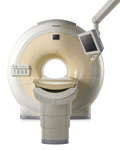
Device Information and Specification
CLINICAL APPLICATION
Whole body
CONFIGURATION
Short bore compact
Standard: Head, body, cardiac, optional phased array: Spine, pediatric, 3rd party connector; Optional SENSE? coils for all applications
SE, Modified-SE, IR (T1, T2, PD), STIR, FLAIR, SPIR, FFE, T1-FFE, T2-FFE, Balanced FFE, TFE, Balanced TFE, Dynamic, Keyhole, 3D, Multi Chunk 3D, Multi Stack 3D, K Space Shutter, MTC, TSE, Dual IR, DRIVE, EPI, Cine, 2DMSS, DAVE, Mixed Mode; Angiography: Inflow MRA, TONE, PCA, CE MRA
128 x 128, 256 x 256,512 x 512,1024 x 1024 (64 for Bold img)
Variable in 1% increments
Lum.: 120 cd/m2; contrast: 150:1
Variable (op. param. depend.)
POWER REQUIREMENTS
380/400 V
| | | | | |  Further Reading: Further Reading: | News & More:
|
|
| |
| | | | | |
| |
|
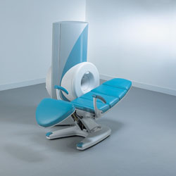
From ONI Medical Systems, Inc.;
MSK-Extreme™ MRI system is a dedicated high field extremity imaging device, designed to provide orthopedic surgeons and other physicians with detailed diagnostic images of the foot, ankle, knee, hand, wrist and elbow, all with the clinical confidence and advantages derived from high field, whole body MRI units. The light weight (less than 650 kg) of the OrthOne System performs rapid patient studies, is easy to operate, has a patient friendly open environment and can be installed in a practice office or hospital, all at a cost similar to a low field extremity machine.
New features include a more powerful operating system that offers increased scan speed as well as a 160-mm knee coil with higher signal to noise ratio, and the option of a CD burner.
Device Information and Specification 16 cm knee, 18 cm lower extremity;; 12.3 cm upper extremity, additional high resolution v-SPEC Coils: 80 mm, 100 mm, or 145 mm. SE, FSE, GE2D, GE3D, Inversion recovery (IR), Driven Equilibrium, Fat Saturation (FS), STIR, MT, PD, Flow Compensation (FC), RF spoiling, MTE, No Phase Wrap (NPW) IMAGING MODES Scout, single, multislice, volume 2D less than 200 msec/image X/Y: 64-512; 2 pixel steps 4,096 grey lvls; 256 lvls in 3D POWER REQUIREMENTS 115VAC, 1phase, 20A; 208VAC, 3 phase, 30A COOLING SYSTEM TYPE LHe with 2 stage cold head 1.25m radial x 1.8m axial | | | | | | | Further Reading: | Basics:
|
|
| |
| | | | | |
| |
|
A type of MRA used to display slow flow across a large volume with a good resolution.
Two data volumes are measured; the flow-rephased images show bright signal, the flow-dephased image show dark flow, whereby in both data volumes the signal of the stationary tissue looks the same. The data volumes are subtracted and the signal intensity of flowing blood remains. | | | | | |
| | | Searchterm 'Display' was also found in the following services: | | | | |
| | |
| |
|
The number of data points collected in one, two or all three directions. Normally used for the 2D in plane sampling. The display matrix may be different from the acquisition matrix, although the latter determines the resolution. Measurement time may be saved by not acquiring raw data lines corresponding to high resolution. Not measured rows are filled with zeroes prior to the image calculation. A square image is the result of an interpolation in phase encoding direction.
See also Zero Filling.

Image Guidance
| | | |
• View the DATABASE results for 'Matrix Size' (4).
| | | | |
| | | | | |
| |
|
(MIP) MRA images can be processed by Maximum Intensity Projection to interactively create different projections. The MIP connects the high intensity dots of the blood vessels in three dimensions, providing an angiogram that can be viewed from any projection.
Each point in the MIP represents the highest intensity experienced in that location on any partition within the imaging volume.
For complete interpretation the base slices should also be reviewed individually and with multiplanar reconstruction (MPR) software. The MIP can then be
displayed in a CINE format or filmed as multiple images acquired from different projections. Although the maximum intensity projection (MIP) algorithm is sensitive to high
signal from inflowing spins, it is also sensitive to high signal of any other etiology. | | | | | |
• View the DATABASE results for 'Maximum Intensity Projection' (5).
| | | | | | Further Reading: | News & More:
|
|
| |
| | | | |
| | |
| | | |
|
| |
 | Look
Ups |
| |