 | Info
Sheets |
| | | | | | | | | | | | | | | | | | | | | | | | |
 | Out-
side |
| | | | |
|
| | | | | |  | Searchterm 'Image' was also found in the following services: | | | | |
|  |  |
| |
|
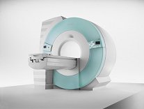
From Siemens Medical Systems;
70 cm + 125 cm + 1.5T and Tim - a combination never seen before in MRI ...
MAGNETOM Espree™s unique open bore design can accommodate more types of patients than other 1.5T systems on the market today, in particular the growing population of obese patients. The power of 1.5T combined with Tim technology boosts signal to noise, which is necessary to adequately image obese patients.
Device Information and Specification
CLINICAL APPLICATION
Whole body
Body, Tim [32 x 8], Tim [76 coil elements with up to 18 RF channels])
GRE, IR, FIR, STIR, TrueIR/FISP, FSE, FLAIR, MT, SS-FSE, MT-SE, MTC, MSE, EPI, 3D DESS//CISS/PSIF, GMR
IMAGING MODES
Single, multislice, volume study, multi angle, multi oblique
Image Processor reconstructing up to 3226 images per second (256 x 256, 25% recFoV)
1024 x 1024 full screen display
| | | | | | | | | | |  Further Reading: Further Reading: | News & More:
|
|
| |
| | | | | |
| |
|
•
In the 1930's, Isidor Isaac Rabi (Columbia University) succeeded in detecting and measuring single states of rotation of atoms and molecules, and in determining the mechanical and magnetic moments of the nuclei.
•
Felix Bloch (Stanford University) and Edward Purcell (Harvard University) developed instruments, which could measure the magnetic resonance in bulk material such as liquids and solids. (Both honored with the Nobel Prize for Physics in 1952.) [The birth of the NMR spectroscopy]
•
In the early 70's, Raymond Damadian (State University of New York) demonstrated with his NMR device, that there are different T1 relaxation times between normal and abnormal tissues of the same type, as well as between different types of normal tissues.
•
In 1973, Paul Lauterbur (State University of New York) described a new imaging technique that he termed Zeugmatography. By utilizing gradients in the magnetic field, this technique was able to produce a two-dimensional image (back-projection). (Through analysis of the characteristics of the emitted radio waves, their origin could be determined.) Peter Mansfield further developed the utilization of gradients in the magnetic field and the mathematically analysis of these signals for a more useful imaging technique. (Paul C Lauterbur and Peter Mansfield were awarded with the 2003 Nobel Prize in Medicine.)
•
1977/78: First images could be presented.
A cross section through a finger by Peter Mansfield and Andrew A. Maudsley.
Peter Mansfield also could present the first image through the abdomen.
•
In 1977, Raymond Damadian completed (after 7 years) the first MR scanner (Indomitable). In 1978, he founded the FONAR Corporation, which manufactured the first commercial MRI scanner in 1980. Fonar went public in 1981.
•
1981: Schering submitted a patent application for Gd-DTPA dimeglumine.
•
1982: The first 'magnetization-transfer' imaging by Robert N. Muller.
•
In 1983, Toshiba obtained approval from the Ministry of Health and Welfare in Japan for the first commercial MRI system.
•
1986: Jürgen Hennig, A. Nauerth, and Hartmut Friedburg (University of Freiburg) introduced RARE (rapid acquisition with relaxation enhancement) imaging. Axel Haase, Jens Frahm, Dieter Matthaei, Wolfgang Haenicke, and Dietmar K. Merboldt (Max-Planck-Institute, Göttingen) developed the FLASH ( fast low angle shot) sequence.
•
1988: Schering's MAGNEVIST gets its first approval by the FDA.
•
In 1991, fMRI was developed independently by the University of Minnesota's Center for Magnetic Resonance Research (CMRR) and Massachusetts General Hospital's (MGH) MR Center.
•
From 1992 to 1997 Fonar was paid for the infringement of it's patents from 'nearly every one of its competitors in the MRI industry including giant multi-nationals as Toshiba, Siemens, Shimadzu, Philips and GE'.
| | | | | |
• View the DATABASE results for 'MRI History' (6).
| | |
• View the NEWS results for 'MRI History' (1).
| | | | | | Further Reading: | | Basics:
|
|
News & More:
| |
| |
| | | | | |
| |
|
Quick Overview Please note that there are different common names for this artifact.
DESCRIPTION
Striped ghosts with a shift of half the field of view
Machine imperfection-based artifacts manifest themselves due to the fact that the odd k-space lines are acquired in a different direction than the even k-space lines. Slight differences in timing result in shifts of the echo in the acquisition window. By the shift theorem, such shifts in the time domain data then produce linear phase differences in the frequency domain data.
Without correction, such phase differences in every second line produce striped ghosts with a shift of half the field of view, so-called Nyquist ghosts. Shifts in the applied magnetic field can also produce similar (but constant in amplitude) ghosts.
This artifact is commonly seen in an EPI image and can arise from both, hardware and sample imperfections.
A further source of machine-based artifact arises from the need to acquire the signal as quickly as possible. For this reason the EPI signal is often acquired during times when the gradients are being switched. Such sampling effectively means that the k-space sampling is not uniform, resulting in ringing artifacts in the image.

Image Guidance
Such artifacts can be minimized by careful setup of the spectrometer and/or correction of the data. For this reasons reference data are often collected, either as a separate scan or embedded in the imaging data.
The non-uniform sampling can be removed by knowing the form of the gradient switching. It is possible to regrid the data onto a uniform k-space grid. | | | |
• View the DATABASE results for 'Machine Imperfection Artifact' (2).
| | | | | | Further Reading: | Basics:
|
|
| |
| | | Searchterm 'Image' was also found in the following services: | | | | |
| | |
| |
|
The number of data points collected in one, two or all three directions. Normally used for the 2D in plane sampling. The display matrix may be different from the acquisition matrix, although the latter determines the resolution. Measurement time may be saved by not acquiring raw data lines corresponding to high resolution. Not measured rows are filled with zeroes prior to the image calculation. A square image is the result of an interpolation in phase encoding direction.
See also Zero Filling.
Image Guidance
| | | |
• View the DATABASE results for 'Matrix Size' (4).
| | | | |
| | | | | |
| |
|
Quick Overview
NAME
Metal, susceptibility
Ferromagnetic metal will cause a magnetic field inhomogeneity, which in turn causes a local signal void, often accompanied by an area of high signal intensity, as well as a distortion of the image.
They create their own magnetic field and dramatically alter precession frequencies of protons in the adjacent tissues. Tissues adjacent to ferromagnetic components become influenced by the induced magnetic field of the metal hardware rather than the parent field and, therefore, either fail to precess or do so at a different frequency and hence do not generate useful signal. Two components contribute to susceptibility artifact, induced magnetism in the ferromagnetic component itself and induced magnetism in protons adjacent to the component. Artifacts from metal may have varied appearances on MRI scans due to different type of metal or configuration of the piece of metal.
The biocompatibility of metallic alloys, stainless steel, cobalt chrome and titanium alloy is based on the presence of a constituent element within the alloy that has the ability to form an adherent oxide coating that is stable, chemically inert and hence biocompatible. In relation to imaging titanium alloys are less ferromagnetic than both cobalt and stainless steel, induce less susceptibility artifact and result in less marked image degradation.
Image Guidance
| | | |
• View the DATABASE results for 'Metal Artifact' (2).
| | | | | | Further Reading: | | Basics:
|
|
News & More:
| |
| |
| | | | |
| | | |
|
| |
 | Look
Ups |
| |


