Magnetic Resonance - Technology Information Portal Welcome to MRI Technology
Info
  Sheets

Out-
      side


 'Amplifier' 
SEARCH FOR    
 
  2 3 5 A B C D E F G H I J K L M N O P Q R S T U V W X Y Z
Result : Searchterm 'Amplifier' found in 3 terms [] and 12 definitions []
previous     11 - 15 (of 15)     
Result Pages : [1]  [2 3]
Searchterm 'Amplifier' was also found in the following services: 
spacer
News  (3)  Resources  (2)  Forum  (1)  
 
Hardware
 
MRI hardware includes the electrical and mechanical components of a scanning device.
The main hardware components for the MRI machine are:
The magnet establishing the B0 field to align the spins.
Within the magnet are the gradient coils for producing variations in B0 in the X, Y, and Z directions to make a localization of the received data possible.
Within the gradient coil or directly on the object being imaged is the radio frequency (RF) coil. This RF coil is used to establish the B1 magnetic field necessary to excite the spinning nuclei. The RF coil also detects the signal emitted from the spins within the object being imaged.
The RF amplifier increases the power of the pulses.
The analog to digital converter converts the received analog raw data into digital values.
Depending on the design of the device and the body part being imaged the patient is positioned inside the magnet (e.g. on a movable table or standing upright).
The MRI scan room is surrounded by a RF shield (Faraday cage).
In addition, a computer console, a display, and a film printer belong to the MRI equipment.

See also the related poll result: 'Most outages of your scanning system are caused by failure of'
Radiology-tip.comradCT Scanner,  Gamma Camera
spacer
Medical-Ultrasound-Imaging.comUltrasound Machine
spacer
 
• Related Searches:
    • Legal Requirements
    • Chiller
    • MRI
    • Analog to Digital Converter
    • Magnet
 
Further Reading:
  Basics:
Imaging Hardware
   by www.fmrib.ox.ac.uk    
  News & More:
Why non-magnetic capacitors matter in medical imaging
Wednesday, 19 February 2020   by www.medicaldesignandoutsourcing.com    
A transportable MRI machine to speed up the diagnosis and treatment of stroke patients
Wednesday, 22 April 2015   by medicalxpress.com    
Magnetic resonance angiography: current status and future directions
Wednesday, 9 March 2011   by www.jcmr-online.com    
Searchterm 'Amplifier' was also found in the following services: 
spacer
Radiology  (1) Open this link in a new windowUltrasound  (6) Open this link in a new window
Matching Network
 
An arrangement of reactive elements (inductors and capacitors) used to transform an input impedance of a given value to an output impedance of a second value. Such circuits are used in interfacing high impedance RF coils to low impedance (usually 50 ohms) transmission lines that feed RF energy to the coil or send the MR signal to an MR preamplifier.
spacer

• View the DATABASE results for 'Matching Network' (3).Open this link in a new window

MRI Resources 
Quality Advice - Liver Imaging - Journals - Non-English - Supplies - Equipment
 
Quadrature CoilInfoSheet: - Coils - 
Intro, 
Overview, 
etc.MRI Resource Directory:
 - Coils -
 
A coil that produces an RF field with circular polarization. The RF power received from the RF power amplifier comes in two signals (quadrature detection), which have a phase difference of 90°. The RF transmit coil converts the power into a circularly polarized RF magnetic field.
Quadrature coils can be used as both, transmit and/or receive coil. When used as a transmitter coil a factor of two power reduction over a linear coil results; as a receiver an increase in SNR of up to a factor of √2, can be achieved.

See also the related poll result: '3rd party coils are better than the original manufacturer coils'
spacer

• View the DATABASE results for 'Quadrature Coil' (2).Open this link in a new window

 
Further Reading:
  News & More:
HEAD AND NECK MRI GRADIENT COIL DESIGN
Thursday, 26 August 1999   by www.imaging.robarts.ca    
Searchterm 'Amplifier' was also found in the following services: 
spacer
News  (3)  Resources  (2)  Forum  (1)  
 
RELAX 0.35T™InfoSheet: - Devices -
Intro, 
Types of Magnets, 
Overview, 
etc.MRI Resource Directory:
 - Devices -
 
www.isoltech.co.kr/english/product/035t.htm 
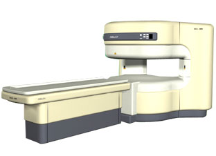
From ISOL Technology
'RELAX is open type MRI system created by making up for the weakness of existing conventional MR systems and applying the strength and the application of the middle to high field MR without uncompromising the image quality.
RELAX offers you a premium mix of form, performance and functionality that are patient and user friendly beyond comparison. - New breed of MRI pursuing - patients comfort'
Device Information and Specification
CLINICAL APPLICATION
Whole body
CONFIGURATION
Open
Head, C-spine, L-spine, TMJ, Knee, Shoulder, General purpose, Phased Array System: 4 digital receiver channels (Up to 12 channels)
SYNCHRONIZATION
ECG/peripheral: Optional/yes, respiratory gating
PULSE SEQUENCES
2D/3D Spin echo, 2D/3D Gradient echo, 2D/3D Fast spin echo, Inversion recovery, 2D/3D Fast gradient echo sequences, FLAIR/STIR, 2D/3D TOF
IMAGING MODES
3D volume imaging (MIP, MPR) MR Angiography package
30 cm
MAGNET TYPE
Permanent
40 cm diameter (patient)
MAGNET WEIGHT
13500 kg
H*W*D
170 x 210 x 130 cm
COOLING SYSTEM TYPE
Water-cooled coil and air-cooled amplifier
STRENGTH
25 - 30 mT/m
5-GAUSS FRINGE FIELD
lower than 2.4 m from the iso-center
Passive and active
spacer

• View the DATABASE results for 'RELAX 0.35T™' (2).Open this link in a new window

Searchterm 'Amplifier' was also found in the following services: 
spacer
Radiology  (1) Open this link in a new windowUltrasound  (6) Open this link in a new window
Radio Frequency Quadrature ArtifactInfoSheet: - Artifacts - 
Case Studies, 
Reduction Index, 
etc.MRI Resource Directory:
 - Artifacts -
 
Quick Overview
Artifact Information
NAME
Radio frequency quadrature
DESCRIPTION
Bright spot in the center of the image, ghosting
REASON
RF detection circuitry problem
HELP
Call the service
Radio frequency quadrature artifacts occur when the detector channels of the quadrature detector are disturbed.
A DC offset of one amplifier output can e.g., produce a bright point in the center of the field of view (see also central point artifact), or a higher gain of one detector channel can generate diagonally ghosting.
mri safety guidance
Image Guidance
Radio frequency quadrature artifacts are technical faults and must be eliminated by the service.
spacer
 
Further Reading:
  News & More:
Magnetic Resonance Imaging (MRI)
2003   by www.hull.ac.uk    
MRI Resources 
Jobs pool - MRI Reimbursement - Diffusion Weighted Imaging - Implant and Prosthesis pool - Research Labs - Resources
 
previous      11 - 15 (of 15)     
Result Pages : [1]  [2 3]
 Random Page
 
Share This Page
FacebookTwitterLinkedIn

MR-TIP    
Community   
User
Pass
Forgot your UserID/Password ?    


How AI will impact MRI :
only diagnostics 
saving time 
reducing cost 
makes planning obsolete 
reduce human knowledge 
not at all 

Look
      Ups


MR-TIP.com uses cookies! By browsing MR-TIP.com, you agree to our use of cookies.

Magnetic Resonance - Technology Information Portal
Member of SoftWays' Medical Imaging Group - MR-TIP • Radiology-TIP • Medical-Ultrasound-Imaging • 
Copyright © 2003 - 2024 SoftWays. All rights reserved. [ 4 May 2024]
Terms of Use | Privacy Policy | Advertising
 [last update: 2024-02-26 03:41:00]