| Info
Sheets |
| | | | | | | | | | | | | | | | | | | | | | | | |
 | Out-
side |
| | | | |
|
| | | | | |
| Result: Searchterm 'Mode'
found in 18 messages |
| Result Pages: 1 [2] 3 4 |
More Results:  Database (85) News Service (93) Resources (25) Database (85) News Service (93) Resources (25) |
|
|
Clifford Thornton
Thu. 30 Jun.16,
17:48
[Start of:
'Max. SAR per second - Whole Body (Normal, 1st Controlled, 2nd Control)'
0 Reply]

 Category: Category:
Safety
|
| Max. SAR per second - Whole Body (Normal, 1st Controlled, 2nd Control) |
Hello fellow imaging technologists & professionals!
I'm involved in the development of a new type of cardiovascular medical device.
This device employs MRI technology/scans to power, guide, and control the medical devices and their active elements.
I conducted some research into the following question, "How much x-ray energy is allowed within a human every sec from a MRI machine?"
With regards to SAR rates, I understand that these are the upper-limits for the various settings for a full-body scan:
Normal setting: Whole body SAR - 2
1st Level Controlled: Whole body SAR - 4
2nd Level Controlled: Whole body SAR - >4
Would you agree with these calculations that I performed, and if not, why? And what would be a better way to calculate this?
For WHOLE BODY SAR:
-SO IF IN NORMAL MODE FOR MRI, THE MAX. ALLOWABLE SAR IS "2" OVER A 6 MIN. PERIOD, THEN
-6 MIN. = 360 SECONDS
-2 / 360 = 0.00555
FOR 1ST LEVEL CONTROLLED:
-SO IF IN 1ST LEVEL CONTROLLED FOR MRI, THE MAX. ALLOWABLE SAR IS "4" OVER A 6 MIN. PERIOD, THEN
-6 MIN. = 360 SECONDS
-4/ 360 = 0.01111
Other questions -- What is the difference between normal setting, 1st conrolled and 2nd controlled?
What is the clinical purpose of these various settings?
Any insights that you would be willing to share in regards to the above would be greatly appreciated!
I was trained and registred as a diagnostic echocardiographer, specializing in cardiovascular ultrasound, therefore I need help with MRI information/specifications. I am now focusing on the medical device field, but this technology/device happens to be highly dependent on MRI technology.
Any help from the group would be greatly appreciated!!
Thanks & regards,
Clifford Thornton
|
| |  Reply to this thread Reply to this thread
(login or register first) | |
Reader Mail
Fri. 3 Apr.15,
09:15
[Start of:
'Experiences with Artroscan C'
1 Reply]
Category:
General
|
| Experiences with Artroscan C |
Is there anyone who have experiences with the Artroscan C by Esaote. My hospital is seriously considering to purchase one or one similar to this model.
There is a flexible coil with this machine which might be used to image the hip the representative said. I have serious doubts how a small flex coil can image an adult hip.
If there is anyone who have experience with such a machine can you provide some feedback please regarding hip and shoulder imaging in particular.
best regards and happy easter to all those celebrating easter. regards David
|
| | View the whole thread | Reply to this thread
(login or register first) | |
Bob Smtih
Thu. 30 Oct.14,
18:41
[Start of:
'What is this white "cloud" on the right side of this MRI?'
0 Reply]
Category:
General
|
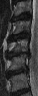
| What is this white "cloud" on the right side of this MRI? |
The following was noted:c2/c3 normal c3/c4 Very minimal anterior ostepphytic ridging is present. There is no spinal stenosis or neural foraminal narrowing. C4/c5 Very minimal anterior ostepphytic ridging is noted. There is no spinal stenosis or neural foraminal narrowing. c5/c6 There is a circumferential disc osteophyte complex present. There is mild central spinal stenosis. The AP diameter of the spinal canal is narrowed to 9mm. The dorsal and ventral CSF spaces remain patent. There is mild to moderate neural foraminal narrowing. c6/c7 a circumferential disc osteophyte complex present. There is mild central spinal stenosis. AP diameter of the spinal canal is narrowed to 9mm. The dorsal and ventral CSF spaces remain patent. There is moderate to severe neural foraminal narrowing. c7/t1 Normal. AP diameter of the spinal canal is 12 mm My question is C5 looks like it is chewed up; weird shading. Does it appear to be more damaged than the report states? Also there seems to be a white "cloud" that goes into the left side of multiple disks. What is the white "cloud"? c3 through c7 are in the image
 MRI SAG T2 MRI SAG T2
|
| | Reply to this thread
(login or register first) | |
John Scott
Thu. 13 Dec.12,
23:30
[Start of:
'Need Pin Out for Hitachi C-Spine Coil 12.8687 MHz HMSA MR-QCS-A810'
0 Reply]
Category:
Devices, Scanner, Machines
|
| Need Pin Out for Hitachi C-Spine Coil 12.8687 MHz HMSA MR-QCS-A810 |
Can someone provide me with the Pin out for the Coil Connector for a Hitachi C-Spine Coil 12.8687 MHz Model Number HMSA MR-QCS-A810?
A few of the wires came unsoldered on the circular connector and I want to have them soldered back on. Thank you.
|
| | Reply to this thread
(login or register first) | |
Steven Ford
Tue. 31 Jan.12,
08:19
[Reply (1 of 2) to:
'RF shimming'
started by: 'Reader Mail'
on Thu. 1 Oct.09]
Category:
Basics and Physics
|
| RF shimming |
For Magnetic fields, the overall field is adjusted to push it up a little bit in one spot and push it down a little bit in another area. The goal is to create a field that's perfectly homogenous.
The RF field created by the transmit coil likewise must be as homogenous as possible, so that the flip angle is constant throughout the imaging volume. In the past, designers have solved this problem by building coils such as the 'birdcage' style that would create a very even amount of energy inside. This is one reason why the transmit coils tend to be large.
With the advent of 3 Tesla and stronger magnets, the RF resonant frequency also rises. RF energy absorbed in the patient rises with the higher frequencies also, and another problem raises its head: it's a lot harder to make a very homogenous RF field. Even if you are scanning phantoms, the inside tends to be subject to different energy than the edges.
But in the human body, there are all sorts of irregular lumps and bumps that absorb RF differently, further complicating matters.
Now, on modern scanners it's possible to perform a magnetic field shim with the patient actually in the magnet in order to compensate for minute changes in the magnet from one exam to another. For super-high field magnets, an RF shim is also a handy thing to do.
If you have a Multi element RF transmit coil (regular phased array coils are just for receiving) you can run a program which selectively turns up the power in some elements so that the overall signal received is maximized. That's an RF shim.
Steven Ford
Professional Imaging Services, Inc.
|
| | View the whole thread | | |
| |
| | Result Pages : 1 [2] 3 4 | |
|
| |
 | Look
Ups |
| |