 | Info
Sheets |
| | | | | | | | | | | | | | | | | | | | | | | | |
 | Out-
side |
| | | | |
|
| | | 'main magnetic field strength' | |
Result : Searchterm 'main magnetic field strength' found in 0 term [ ] and 1 definition [ ] and 1 definition [ ], (+ 20 Boolean[ ], (+ 20 Boolean[ ] results ] results
| | 1 - 5 (of 21) nextResult Pages : [1] [2 3 4 5] |  | |  | Searchterm 'main magnetic field strength' was also found in the following service: | | | | |
| |  |
| |
|
| | | | | | • Share the entry 'B0':    | | | | |  Further Reading: Further Reading: | | Basics:
|
|
News & More:
| |
| |
| | | | |  |
| |
|
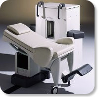
Developed by GE Lunar; the ARTOSCAN™-M is designed specifically for in-office musculoskeletal imaging. ARTOSCAN-M's compact, modular design allows placing within a clinical environment, bringing MRI to the patient. Patients re main outside the magnet at all times during the examinations, enabling constant patient-technologist contact. ARTOSCAN-M requires no special RF room, magnetic shielding, special power supply or air conditioning.
The C-SCAN™ (also known as Artoscan C) is developed from the ARTOSCAN™ - M, with a new computer platform.
Device Information and Specification
CLINICAL APPLICATION
Dedicated extremity
SE, GE, IR, STIR, FSE, 3D CE, GE-STIR, 3D GE, ME, TME, HSE
SLICE THICKNESS
2D: 2 mm - 10 mm;
3D: 0.6 mm - 10 mm
4,096 gray lvls, 256 lvls in 3D
POWER REQUIREMENTS
100/110/200/220/230/240V
| | | |
• View the DATABASE results for 'ARTOSCAN™ - M' (3).
| | | | |
| | | | | |
| |
|
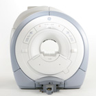
From GE Healthcare;
The GE Signa HDx MRI system is a whole body magnetic resonance scanner designed to support high resolution, high signal to noise ratio, and short scan times.
The 1.5T Signa HDx MR Systems is a modification of the currently marketed GE 1.5T machines, with the main difference being the change to the receive chain architecture that includes a thirty two independent receive channels, and allows for future expansion in 16 channel increments. The overall system has been improved with a simplified user interface
and a single 23" liquid crystal display, improved multi channel surface coil connectivity, and an improved image reconstruction architecture known as the Volume Recon Engine (VRE).
Device Information and Specification CLINICAL APPLICATION Whole body CONFIGURATION Compact short bore Standard: SE, IR, 2D/3D GRE and SPGR, Angiography: 2D/3D TOF, 2D/3D Phase Contrast; 2D/3D FSE, 2D/3D FGRE and FSPGR, SSFP, FLAIR, EPI, optional: 2D/3D Fiesta, FGRET, Spiral, Tensor, 2D 0.7 mm to 20 mm; 3D 0.1 mm to 5 mm 128x512 steps 32 phase encode POWER REQUIREMENTS 480 or 380/415 less than 0.03 L/hr liquid helium | | | | | |
| | | Searchterm 'main magnetic field strength' was also found in the following service: | | | | |
| | |
| |
|
Quick Overview Please note that there are different common names for this artifact.
DESCRIPTION
Black or bright band
During frequency encoding, fat protons precess slower than water protons in the same slice because of their magnetic shielding. Through the difference in resonance frequency between water and fat, protons at the same location are misregistrated (dislocated) by the Fourier transformation, when converting MRI signals from frequency to spatial do main. This chemical shift misregistration cause accentuation of any fat-water interfaces along the frequency axis and may be mistaken for pathology. Where fat and water are in the same location, this artifact can be seen as a bright or dark band at the edge of the anatomy.
Protons in fat and water molecules are separated by a chemical shift of about 3.5 ppm. The actual shift in Hertz (Hz) depends on the magnetic field strength of the magnet being used. Higher field strength increases the misregistration, while in contrast a higher gradient strength has a positive effect. For a 0.3 T system operating at 12.8 MHz the shift will be 44.8 Hz compared with a 223.6 Hz shift for a 1.5 T system operating at 63.9 MHz.

Image Guidance
| | | |
• View the DATABASE results for 'Chemical Shift Artifact' (7).
| | | | | | Further Reading: | Basics:
|
|
News & More:
| |
| |
| | | | | |
| |
|

It is important to remember when working around a superconducting magnet that the magnetic field is always on. Under usual working conditions the field is never turned off. Attention must be paid to keep all ferromagnetic items at an adequate distance from the magnet. Ferromagnetic objects which came accidentally under the influence of these strong magnets can injure or kill individuals in or nearby the magnet, or can seriously damage every hardware, the magnet itself, the cooling system, etc..
See MRI resources Accidents.
The doors leading to a magnet room should be closed at all times except when entering or exiting the room. Every person working in or entering the magnet room or adjacent rooms with a magnetic field has to be instructed about the dangers. This should include the patient, intensive-care staff, and maintenance-, service- and cleaning personnel, etc..
The 5 Gauss limit defines the 'safe' level of static magnetic field exposure. The value of the absorbed dose is fixed by the authorities to avoid heating of the patient's tissue and is defined by the specific absorption rate.
Leads or wires that are used in the magnet bore during imaging procedures, should not form large-radius wire loops. Leg-to-leg and leg-to-arm skin contact should be prevented in order to avoid the risk of burning due to the generation of high current loops if the legs or arms are allowed to touch. The patient's skin should not be in contact with the inner bore of the magnet.
The outflow from cryogens like liquid helium is improbable during normal operation and not a real danger for patients.
The safety of MRI contrast agents is tested in drug trials and they have a high compatibility with very few side effects. The variations of the side effects and possible contraindications are similar to X-ray contrast medium, but very rare. In general, an adverse reaction increases with the quantity of the MRI contrast medium and also with the osmolarity of the compound.
See also 5 Gauss Fringe Field, 5 Gauss Line, Cardiac Risks, Cardiac Stent, dB/dt, Legal Requirements, Low Field MRI, Magnetohydrodynamic Effect, MR Compatibility, MR Guided Interventions, Claustrophobia, MRI Risks and Shielding. | | | | | | | | |
• View the DATABASE results for 'MRI Safety' (42).
| | |
• View the NEWS results for 'MRI Safety' (13).
| | | | | | Further Reading: | Basics:
|
|
News & More:
| |
| |
| | | | |
| | | 1 - 5 (of 21) nextResult Pages : [1] [2 3 4 5] |
| |
|
| |
 | Look
Ups |
| |


