 | Info
Sheets |
| | | | | | | | | | | | | | | | | | | | | | | | |
 | Out-
side |
| | | | |
|
| | | | |
Result : Searchterm 'Tesla' found in 3 terms [ ] and 38 definitions [ ] and 38 definitions [ ] ]
| | previous 11 - 15 (of 41) nextResult Pages : [1] [2 3 4 5 6 7 8 9] |  | |  | Searchterm 'Tesla' was also found in the following services: | | | | |
| |  |
| |
|
Magnetic forces are fundamental forces that arise due to the movement of electrical charge. Maxwell's equations describe the origin and behavior of the fields that govern these forces. Thus, magnetism is seen whenever electrically charged particles are in motion. This can arise either from movement of electrons in an electric current, resulting in 'electromagnetism', or from the quantum-mechanical orbital motion (there is no orbital motion of electrons around the nucleus like planets around the sun, but there is an 'effective electron velocity') and spin of electrons, resulting in what are known as ' permanent magnets'.
The physical cause of the magnetism of objects, as distinct from electrical currents, is the atomic magnetic dipole. Magnetic dipoles, or magnetic moments, result on the atomic scale from the two kinds of movement of electrons. The first is the orbital motion of the electron around the nucleus this motion can be considered as a current loop, resulting in an orbital dipole magnetic moment along the axis of the nucleus. The second, much stronger, source of electronic magnetic moment is due to a quantum mechanical property called the spin dipole magnetic moment.
Gauss (G) and tesla (T) are units to define the intensity of magnetic fields. One tesla is equivalent to 10 000 gauss.
Typically, the field strength of MRI scanners is between 0.15 T and 3 T.
See also Diamagnetism, Paramagnetism, Superparamagnetism, and Ferromagnetism. | | | |
• View the NEWS results for 'Magnetism' (1).
| | | | |  Further Reading: Further Reading: | | Basics:
|
|
News & More:
| |
| |
| | | Searchterm 'Tesla' was also found in the following services: | | | | |
| | |
| |
|
( STIR) Also called Short Tau ( t) ( inversion time) Inversion Recovery. STIR is a fat suppression technique with an inversion time t = T1 ln2 where the signal of fat is zero ( T1 is the spin lattice relaxation time of the component that should be suppressed). To distinguish two tissue components with this technique, the T1 values must be different. Fluid Attenuation Inversion Recovery ( FLAIR) is a similar technique to suppress water.
Inversion recovery doubles the distance spins will recover, allowing more time for T1 differences. A 180° preparation pulse inverts the net magnetization to the negative longitudinal magnetization prior to the 90° excitation pulse.
This specialized application of the inversion recovery sequence set the inversion time ( t) of the sequence at 0.69 times the T1 of fat. The T1 of fat at 1.5 Tesla is approximately 250 with a null point of 170 ms while at 0.5 Tesla its 215 with a 148 ms null point. At the moment of excitation, about 120 to 170 ms after the 180° inversion pulse (depending of the magnetic field) the magnetization of the fat signal has just risen to zero from its original, negative, value and no fat signal is available to be flipped into the transverse plane.
When deciding on the optimal T1 time, factors to be considered include not only the main field strength, but also the tissue to be suppressed and the anatomy. In comparison to a conventional spin echo where tissues with a short T1 are bright due to faster recovery, fat signal is reversed or darkened.
Because body fluids have both a long T1 and a long T2, it is evident that STIR offers the possibility of extremely sensitive detection of body fluid. This is of course, only true for stationary fluid such as edema, as the MRI signal of flowing fluids is governed by other factors.
See also Fat Suppression and Inversion Recovery Sequence. | | | | | |
• View the DATABASE results for 'Short T1 Inversion Recovery' (3).
| | | | | | Further Reading: | Basics:
|
|
News & More:
| |
| |
| | | | | |
| |
|
(SAR) The Specific Absorption Rate is defined as the RF power absorbed per unit of mass of an object, and is measured in watts per kilogram (W/kg).
The SAR describes the potential for heating of the patient's tissue due to the application of the RF energy necessary to produce the MR signal. Inhomogeneity of the RF field leads to a local exposure where most of the absorbed energy is applied to one body region rather than the entire person, leading to the concept of a local SAR. Hot spots may occur in the exposed tissue, to avoid or at least minimize effects of such theoretical complications, the frequency and the power of the radio frequency irradiation should be kept at the lowest possible level. Averaging over the whole body leads to the global SAR.
It increases with field strength, radio frequency power and duty cycle, transmitter-coil type and body size. The doubling of the field strength from 1.5 Tesla (1.5T) to 3 Tesla ( 3T) leads to a quadrupling of SAR. In high and ultrahigh fields, some of the multiple echo, multiple-slice pulse sequences may create a higher SAR than recommended by the agencies. SAR can be reduced by lower flip angle and longer repetition times, which could potentially affect image contrast.
Normally no threatening increase in temperature could be shown. Even in high magnetic fields, the local temperature increases not more than 1°C. 2.1°C is the highest measured increase in skin temperature. Eddy currents may heat up implants and thus may cause local heating.
FDA SAR limits:
•
Whole body: 4W/kg/15-minute exposure averaged;
•
Head: 3W/kg/10-minute exposure averaged;
•
Head or torso: 8W/kg/5 minute exposure per gram of tissue;
•
Extremities: 12W/kg/5 minute exposure per gram of tissue.
IEC (International Electrotechnical Commission) SAR limits of some European countries:
All limits are averaged over 6 minutes.
•
Level 0 (normal operating mode): Whole body 2W/kg; Head 3.2W/kg; Head or Torso (local) 10W/kg;
Extremities (local) 20W/kg;
•
Level I (first level controlled operating mode): Whole body 4W/kg; Head 3.2W/kg; Head or Torso (local) 10W/kg; Extremities (local) 20W/kg;
•
Level II (second level controlled operating mode): All values are over Level I values.
(For more details: IEC 60601-2-33 (2002))
In most countries standard MRI systems are limited to a maximum SAR of 4 W/kg, so most scanning in level II is impossible.
For Level I, in addition to routine monitoring, particular caution must be exercised for patients who are sensitive to temperature increases or to RF energy.
For Japan different SAR limits are valid. | | | |
• View the DATABASE results for 'Specific Absorption Rate' (8).
| | |
• View the NEWS results for 'Specific Absorption Rate' (1).
| | | | | | Further Reading: | Basics:
|
|
News & More:
| |
| |
| | | Searchterm 'Tesla' was also found in the following services: | | | | |
| | |
| |
|
| | | |
• View the DATABASE results for 'B0' (41).
| | | | | | Further Reading: | Basics:
|
|
News & More:
| |
| |
| | | Searchterm 'Tesla' was also found in the following services: | | | | |
| | |
| |
|
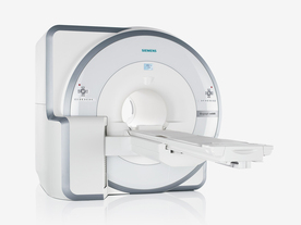
FDA cleared and CE Mark 2011.
The Biograph mMR has a fully-integrated design for simultaneous PET/MRI imaging. The dedicated hardware includes solid-state, avalanche photodiode PET detector and adapted, PET-compatible MR coils.
The possibility of truly simultaneous operation allows the acquisition of several magnetic resonance imaging ( MRI) sequences during the positron emission tomography (PET) scan, without increasing the examination time.
See also Hybrid Imaging.
Device Information and Specification
CLINICAL APPLICATION
Whole Body
CONFIGURATION
Simultaneous PET/MRI
26 cm (typical overlap 23%)
A-P 45, R-L 50, H-F 50 cm
PET RING DIAMETER
65.6 cm
PATIENT SCAN RANGE
199 cm
HORIZONTAL SPEED
200 mmsec
PET DETECTOR
Solid state, 4032 avalanche photo diodes
DETECTOR SCINTILLATION MATERIAL
LSO, 28672 crystals
CRYSTAL SIZE
4 x 4 x 20 mm
DIMENSION H*W*D (gantry included)
335 x 230 x 242 cm (finshed covers)
COOLING SYSTEM
PET system: water; MRI system: water
Aautomatic, patient specific shim; active shim 3 linear and 5 non-linear channels (seond order)
POWER REQUIREMENTS
380 / 400 / 420 / 440 / 460 / 480 V, 3-phase + ground; Total system 110kW
| | | | | | | Further Reading: | Basics:
|
|
News & More:
| |
| |
| | | | |
| | | |
|
| |
 | Look
Ups |
| |


