 | Info
Sheets |
| | | | | | | | | | | | | | | | | | | | | | | | |
 | Out-
side |
| | | | |
|
| | | | |
Result : Searchterm 'T2 Time' found in 1 term [ ] and 16 definitions [ ] and 16 definitions [ ], (+ 17 Boolean[ ], (+ 17 Boolean[ ] results ] results
| | previous 21 - 25 (of 34) nextResult Pages : [1] [2 3 4] [5 6 7] |  | |  | Searchterm 'T2 Time' was also found in the following services: | | | | |
| |  |
| |
|
(FSE) In the pulse sequence timing diagram, a fast spin echo sequence with an echo train length of 3 is illustrated.
This sequence is characterized by a series of rapidly applied 180° rephasing pulses and multiple echoes, changing the phase encoding gradient for each echo.
The echo time TE may vary from echo to echo in the echo train. The echoes in the center of the K-space (in the case of linear k-space acquisition) mainly produce the type of image contrast, whereas the periphery of K-space determines the spatial resolution. For example, in the middle of K-space the late echoes of T2 weighted images are encoded. T1 or PD contrast is produced from the early echoes.
The benefit of this technique is that the scan duration with, e.g. a turbo spin echo turbo factor / echo train length of 9, is one ninth of the time. In T1 weighted and proton density weighted sequences, there is a limit to how large the ETL can be (e.g. a usual ETL for T1 weighted images is between 3 and 7). The use of large echo train lengths with short TE results in blurring and loss of contrast. For this reason, T2 weighted imaging profits most from this technique.
In T2 weighted FSE images, both water and fat are hyperintense. This is because the succession of 180° RF pulses reduces the spin spin interactions in fat and increases its T2 decay time. Fast spin echo (FSE) sequences have replaced conventional T2 weighted spin echo sequences for most clinical applications. Fast spin echo allows reduced acquisition times and enables T2 weighted breath hold imaging, e.g. for applications in the upper abdomen.
In case of the acquisition of 2 echoes this type of a sequence is named double fast spin echo / dual echo sequence, the first echo is usually density and the second echo is T2 weighted image. Fast spin echo images are more T2 weighted, which makes it difficult to obtain true proton density weighted images. For dual echo imaging with density weighting, the TR should be kept between 2000 - 2400 msec with a short ETL (e.g., 4).
Other terms for this technique are:
Turbo Spin Echo
Rapid Imaging Spin Echo,
Rapid Spin Echo,
Rapid Acquisition Spin Echo,
Rapid Acquisition with Refocused Echoes
| | | | | | | | | | | | |  Further Reading: Further Reading: | | Basics:
|
|
News & More:
| |
| |
| | | | | |
| |
|
Device Information and Specification CLINICAL APPLICATION Whole body SE, FE, IR, STIR, FFE, DEFFE, DESE, TSE, DETSE, Single shot SE, DRIVE, Balanced FFE, MRCP, Fluid Attenuated Inversion Recovery, Turbo FLAIR, IR-TSE, T1-STIR TSE, T2-STIR TSE, Diffusion Imaging, 3D SE, 3D FFE, Contrast Perfusion Analysis, MTC;; Angiography: CE-ANGIO, MRA 2D, 3D TOFOpen x 47 cm x infinite (side-first patient entry) POWER REQUIREMENTS 400/480 V | | | |
• View the DATABASE results for 'Panorama 0.6T™' (2).
| | | | |
| | | | | |
| |
|
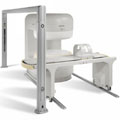
From Philips Medical Systems;
the Panorama 0.23 T, providing a new design optimized for patient comfort, faster reconstruction time than before (300 images/second) and new gradient
specifications. Philips' Panorama 0.23 T I/T supports MR-guided interventions, resulting in minimally invasive procedures, more targeted surgery, reduced recovery time and shorter hospital stays. Optional OptoGuide functionality enables real- time needle tracking. Philips' Panorama 0.23 TPanorama 0.2 R/T is the first and only open MRI system to enable radiation therapy planning using MR data sets. The Panorama also features the new and consistent Philips User Interface, an essential element of the Vequion clinical IT family of products and services.
Device Information and Specification CLINICAL APPLICATION Whole body SE, FE, IR, FFE, DEFFE, DESE, TSE, DETSE, Single shot SE, DRIVE, Balanced FFE, MRCP, Fluid Attenuated Inversion Recovery, Turbo FLAIR, IR-TSE, T1-STIR TSE, T2-STIR TSE, Diffusion Imaging, 3D SE, 3D FFE, MTC;; Angiography: CE-ANGIO, MRA 2D, 3D TOFOpen x 46 cm x infinite (side-first patient entry) POWER REQUIREMENTS 400/480 V COOLING SYSTEM TYPE Closed loop chilled water ( chiller included) | | | |
• View the DATABASE results for 'Panorama 0.23T™' (2).
| | | | | | Further Reading: | News & More:
|
|
| |
| | | Searchterm 'T2 Time' was also found in the following services: | | | | |
| | |
| |
|
(IR) The inversion recovery pulse sequence produces signals, which represent the longitudinal magnetization existing after the application of a 180° radio frequency pulse that rotates the magnetization Mz into the negative plane. After an inversion time (TI - time between the starting 180° pulse and the following 90° pulse), a further 90° RF pulse tilts some or all of the z-magnetization into the xy-plane, where the signal is usually rephased with a 180° pulse as in the spin echo sequence. During the initial time period, various tissues relax with their intrinsic T1 relaxation time.
In the pulse sequence timing diagram, the basic inversion recovery sequence is illustrated. The 180° inversion pulse is attached prior to the 90° excitation pulse of a spin echo acquisition.
See also the Pulse Sequence Timing Diagram. There you will find a description of the components.
The inversion recovery sequence has the advantage, that it can provide very strong contrast between tissues having different T1 relaxation times or to suppress tissues like fluid or fat.
But the disadvantage is, that the additional inversion radio frequency RF pulse makes this sequence less time efficient than the other pulse sequences.
Contrast values:
PD weighted: TE: 10-20 ms, TR: 2000 ms, TI: 1800 ms
T1 weighted: TE: 10-20 ms, TR: 2000 ms, TI: 400-800 ms
T2 weighted: TE: 70 ms, TR: 2000 ms, TI: 400-800 ms
See also Inversion Recovery, Short T1 Inversion Recovery, Fluid Attenuation Inversion Recovery, and Acronyms for 'Inversion Recovery Sequence' from different manufacturers. | | | | | |
• View the DATABASE results for 'Inversion Recovery Sequence' (8).
| | | | | | Further Reading: | | Basics:
|
|
News & More:
| |
| |
| | | | | |
| |
|
(GRE - sequence) A gradient echo is generated by using a pair of bipolar gradient pulses. In the pulse sequence timing diagram, the basic gradient echo sequence is illustrated. There is no refocusing 180° pulse and the data are sampled during a gradient echo, which is achieved by dephasing the spins with a negatively pulsed gradient before they are rephased by an opposite gradient with opposite polarity to generate the echo.
See also the Pulse Sequence Timing Diagram. There you will find a description of the components.
The excitation pulse is termed the alpha pulse α. It tilts the magnetization by a flip angle α, which is typically between 0° and 90°. With a small flip angle there is a reduction in the value of transverse magnetization that will affect subsequent RF pulses.
The flip angle can also be slowly increased during data acquisition (variable flip angle: tilt optimized nonsaturation excitation).
The data are not acquired in a steady state, where z-magnetization recovery and destruction by ad-pulses are balanced.
However, the z-magnetization is used up by tilting a little more of the remaining z-magnetization into the xy-plane for each acquired imaging line.
Gradient echo imaging is typically accomplished by examining the FID, whereas the read gradient is turned on for localization of the signal in the readout direction. T2* is the characteristic decay time constant associated with the FID. The contrast and signal generated by a gradient echo depend on the size of the longitudinal magnetization and the flip angle.
When α = 90° the sequence is identical to the so-called partial saturation or saturation recovery pulse sequence.
In standard GRE imaging, this basic pulse sequence is repeated as many times as image lines have to be acquired.
Additional gradients or radio frequency pulses are introduced with the aim to spoil to refocus the xy-magnetization at the moment when the spin system is subject to the next α pulse.
As a result of the short repetition time, the z-magnetization cannot fully recover and after a few initial α pulses there is an equilibrium established between z-magnetization recovery and z-magnetization reduction due to the α pulses.
Gradient echoes have a lower SAR, are more sensitive to field inhomogeneities and have a reduced crosstalk, so that a small or no slice gap can be used.
In or out of phase imaging depending on the selected TE (and field strength of the magnet) is possible.
As the flip angle is decreased, T1 weighting can be maintained by reducing the TR.
T2* weighting can be minimized by keeping the TE as short as possible, but pure T2 weighting is not possible.
By using a reduced flip angle, some of the magnetization value remains longitudinal (less time needed to achieve full recovery) and for a certain T1 and TR, there exist one flip angle that will give the most signal, known as the "Ernst angle".
Contrast values:
PD weighted: Small flip angle (no T1), long TR (no T1) and short TE (no T2*)
T1 weighted: Large flip angle (70°), short TR (less than 50ms) and short TE
T2* weighted: Small flip angle, some longer TR (100 ms) and long TE (20 ms)
Classification of GRE sequences can be made into four categories:
See also Gradient Recalled Echo Sequence, Spoiled Gradient Echo Sequence, Refocused Gradient Echo Sequence, Ultrafast Gradient Echo Sequence.
| | | | | |
• View the DATABASE results for 'Gradient Echo Sequence' (70).
| | | | | | Further Reading: | Basics:
|
|
News & More:
| |
| |
| | | | |
| | | |
|
| |
 | Look
Ups |
| |


