Magnetic Resonance - Technology Information Portal Welcome to MRI Technology
Info
  Sheets

Out-
      side


 'Slice Thickness' 
SEARCH FOR    
 
  2 3 5 A B C D E F G H I J K L M N O P Q R S T U V W X Y Z
Result : Searchterm 'Slice Thickness' found in 1 term [] and 63 definitions []
1 - 5 (of 64)     next
Result Pages : [1]  [2 3 4 5 6 7 8 9 10 11 12 13]
Searchterm 'Slice Thickness' was also found in the following services: 
spacer
Forum  (2)  
 
Slice Thickness
 
(THK) The thickness of an imaging slice. As the slice profile may not be sharp edged, a criterion such as the distance between the points at half the sensitivity of the maximum (FWHM) or the equivalent rectangular width (the width of a rectangular slice profile with the same maximum height and same area) is used to determine thickness.
mri safety guidance
Image Guidance
For the image quality its important to choose the best fitting slice thickness for an examination. When a small item is entirely contained within the slice thickness with other tissue of differing signal intensity then the resulting signal displayed on the image is a combination of these two intensities. If the slice is the same thickness or thinner than the small structure, only that structures signal intensity is displayed on the image. This partial volume averaging effect explains the vanishing of fine details by choosing slices too large for the scanned object.

See also Partial Volume Artifact.
spacer
 
• Share the entry 'Slice Thickness':  Facebook  Twitter  LinkedIn  
 
• Related Searches:
    • Slice Select Gradient
    • Cervical Spine MRI
    • Image Quality
    • Breast MRI
    • Slice Profile
 
Further Reading:
  Basics:
MRI Quality Control Program
   by www.simplyphysics.com    
  News & More:
Optimizing Musculoskeletal MR
   by rad.usuhs.mil    
Searchterm 'Slice Thickness' was also found in the following service: 
spacer
Ultrasound  (3) Open this link in a new window
BandwidthForum -
related threads
 
(BW) Bandwidth is a measure of frequency range, the range between the highest and lowest frequency allowed in the signal. For analog signals, which can be mathematically viewed as a function of time, bandwidth is the width, measured in Hertz of a frequency range in which the signal's Fourier transform is nonzero.
The receiver (or acquisition) bandwidth (rBW) is the range of frequencies accepted by the receiver to sample the MR signal. The receiver bandwidth is changeable (see also acronyms for 'bandwidth' from different manufacturers) and has a direct relationship to the signal to noise ratio (SNR) (SNR = 1/squareroot (rBW). The bandwidth depends on the readout (or frequency encoding) gradient strength and the data sampling rate (or dwell time).
Bandwidth is defined by BW = Sampling Rate/Number of Samples.
A smaller bandwidth improves SNR, but can cause spatial distortions, also increases the chemical shift. A larger bandwidth reduces SNR (more noise from the outskirts of the spectrum), but allows faster imaging.
The transmit bandwidth refers to the RF excitation pulse required for slice selection in a pulse sequence. The slice thickness is proportional to the bandwidth of the RF pulse (and inversely proportional to the applied gradient strength). Lowering the pulse bandwidth can reduce the slice thickness.
mri safety guidance
Image Guidance
A higher bandwidth is used for the reduction of chemical shift artifacts (lower bandwidth - more chemical shift - longer dwell time - but better signal to noise ratio). Narrow receive bandwidths accentuate this water fat shift by assigning a smaller number of frequencies across the MRI image. This effect is much more significant on higher field strengths. At 1.5 T, fat and water precess 220 Hz apart, which results in a higher shift than in Low Field MRI.
Lower bandwidth (measured in Hz) = higher water fat shift (measured in pixel shift).

See also Aliasing, Aliasing Artifact, Frequency Encoding, and Chemical Shift Artifact.
spacer

• View the DATABASE results for 'Bandwidth' (19).Open this link in a new window

 
Further Reading:
  Basics:
Bandwidth
   by en.wikipedia.org    
  News & More:
Automated Quality Assurance for Magnetic Resonance Image with Extensions to Diffusion Tensor Imaging(.pdf)
   by scholar.lib.vt.edu    
A Real-Time Navigator Approach to Compensating for Motion Artifacts in Coronary Magnetic Resonance Angiography
   by www.cs.nyu.edu    
MRI Resources 
Journals - Implant and Prosthesis - Most Wanted - Musculoskeletal and Joint MRI - Lung Imaging - Non-English
 
Time of Flight AngiographyInfoSheet: - Sequences - 
Intro, 
Overview, 
Types of, 
etc.MRI Resource Directory:
 - MRA -
 
(TOF) The time of flight angiography is used for the imaging of vessels. Usually the sequence type is a gradient echo sequences with short TR, acquired with slices perpendicular to the direction of blood flow.
The source of diverse flow effects is the difference between the unsaturated and presaturated spins and creates a bright vascular image without the invasive use of contrast media. Flowing blood moves unsaturated spins from outside the slice into the imaging plane. These completely relaxed spins have full equilibrium magnetization and produce (when entering the imaging plane) a much higher signal than stationary spins if a gradient echo sequence is generated. This flow related enhancement is also referred to as entry slice phenomenon, or inflow enhancement.
Performing a presaturation slab on one side parallel to the slice can selectively destroy the MR signal from the in-flowing blood from this side of the slice. This allows the technique to be flow direction sensitive and to separate arteriograms or venograms. When the local magnetization of moving blood is selectively altered in a region, e.g. by selective excitation, it carries the altered magnetization with it when it moves, thus tagging the selected region for times on the order of the relaxation times.
For maximum flow signal, a complete new part of blood has to enter the slice every repetition (TR) period, which makes time of flight angiography sensitive to flow-velocity. The choice of TR and slice thickness should be appropriate to the expected flow-velocities because even small changes in slice thickness influences the performance of the TOF sequence. The use of sequential 2 dimensional Fourier transformation (2DFT) slices, 3DFT slabs, or multiple 3D slabs (chunks) are depending on the coverage required and the range of flow-velocities.
3D TOF MRA is routinely used for evaluating the Circle of Willis.

See also Magnetic Resonance Angiography and Contrast Enhanced Magnetic Resonance Angiography.
 
Images, Movies, Sliders:
 TOF-MRA Circle of Willis Inverted MIP  Open this link in a new window
    

 Circle of Willis, Time of Flight, MIP  Open this link in a new window
    
SlidersSliders Overview

 
Radiology-tip.comradCT Angiography,  Coronary Angiogram
spacer
Medical-Ultrasound-Imaging.comColor Power Angio,  Doppler Ultrasound
spacer

• View the DATABASE results for 'Time of Flight Angiography' (11).Open this link in a new window

 
Further Reading:
  Basics:
MR–ANGIOGRAPHY(.pdf)
  News & More:
Magnetic resonance angiography: current status and future directions
Wednesday, 9 March 2011   by www.jcmr-online.com    
Searchterm 'Slice Thickness' was also found in the following services: 
spacer
Forum  (2)  
 
AIRIS II™InfoSheet: - Devices -
Intro, 
Types of Magnets, 
Overview, 
etc.MRI Resource Directory:
 - Devices -
 
www.hitachimed.com/products/airis_2.asp 
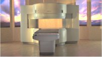
From Hitachi Medical Systems America Inc.;
the AIRIS II, an entry in the diagnostic category of open MR systems, was designed by Hitachi Medical Systems America Inc. (Twinsburg, OH, USA) and Hitachi Medical Corp. (Tokyo) and is manufactured by the Tokyo branch. A 0.3 T field-strength magnet and phased array coils deliver high image quality without the need for a tunnel-type high-field system, thereby significantly improving patient comfort not only for claustrophobic patients.
Device Information and Specification
CLINICAL APPLICATION
Whole body
CONFIGURATION
Vertical Field, Open MRI
QD Head, MA Head and Neck, QD C-Spine, MA or QD Shoulder, MA CTL Spine, QD Knee, Neck, QD TMJ, QD Breast, QD Flex Body (4 sizes), Small and Large Extrem., QD Wrist, MA Foot and Ankle (WIP), PVA (WIP)
SYNCHRONIZATION
Cardiac gating, ECG/peripheral, respiratory gating (2 modes)
PULSE SEQUENCES
SE, GE, GR, IR, FIR, STIR, FSE, ss-FSE, FLAIR, EPI -DWI, SE-EPI, ms - EPI, SSP, MTC, SARGE, RSSG, TRSG, MRCP, Angiography: CE, 2D/3D TOF
IMAGING MODES
Single, multislice, volume study
TR
SE: 30 - 10,000msec GE: 20 - 10,000msec IR: 50 - 16,700msec FSE: 200 - 16,7000msec
TE
SE : 10 - 250msec IR: 10 -250msec GE: 5 - 50 msec FSE: 15 - 2,000
SINGLE/MULTI SLICE
0.05 sec/image (256 x 256)
FOV
5cm to 42 cm continuous
2D: 2 - 100 mm; 3D: 0.5 - 5 mm
1280 x 1024
MEASURING MATRIX
512 x 512
PIXEL INTENSITY
Level Range: -2,000 to +4,000
Sub millimeter
MAGNET TYPE
Self-shielded, permanent
BORE DIAMETER
or W x H
110 x 43 cm
MAGNET WEIGHT
15,700 kg
H*W*D
79 x 111 x 73 cm
POWER REQUIREMENTS
208/220/240 V, single phase
COOLING SYSTEM TYPE
Air-cooled
STRENGTH
15 mT/m
2.0 m lateral, 2.5 m vert./long
Auto shimming, 3-axis/patient, and volume shim
spacer

• View the DATABASE results for 'AIRIS II™' (2).Open this link in a new window

Searchterm 'Slice Thickness' was also found in the following service: 
spacer
Ultrasound  (3) Open this link in a new window
ARTOSCAN™ - MInfoSheet: - Devices -
Intro, 
Types of Magnets, 
Overview, 
etc.MRI Resource Directory:
 - Devices -
 
www.gemedicalsystems.com/rad/mri/products/artoscan/specs.html 
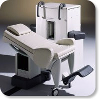
Developed by GE Lunar; the ARTOSCAN™-M is designed specifically for in-office musculoskeletal imaging. ARTOSCAN-M's compact, modular design allows placing within a clinical environment, bringing MRI to the patient. Patients remain outside the magnet at all times during the examinations, enabling constant patient-technologist contact. ARTOSCAN-M requires no special RF room, magnetic shielding, special power supply or air conditioning.
The C-SCAN™ (also known as Artoscan C) is developed from the ARTOSCAN™ - M, with a new computer platform.
Device Information and Specification
CLINICAL APPLICATION
Dedicated extremity
CONFIGURATION
Closed
Linear and dual phased array coil, knee, ankle, wrist coils
PULSE SEQUENCES
SE, GE, IR, STIR, FSE, 3D CE, GE-STIR, 3D GE, ME, TME, HSE
IMAGING MODES
Single, multislice, volume study, fast scan, multi slab, cine
TR
12 - 5,000 msec
TE
5 - 220 msec
SINGLE SLICE
0.8 sec/image
MULTISLICE
0.8 sec/image
FOV
10 - 20 cm
SLICE THICKNESS
2D: 2 mm - 10 mm;
3D: 0.6 mm - 10 mm
512 x 512
MEASURING MATRIX
256 x 256 maximum
PIXEL INTENSITY
4,096 gray lvls, 256 lvls in 3D
MAGNET TYPE
Ferrite Permanent
MAGNET WEIGHT
965 kg
POWER REQUIREMENTS
100/110/200/220/230/240V
STRENGTH
10 mT/m
5 GAUSS FRINGE FIELD, radial/axial
28 cm/60 cm
Passive
spacer

• View the DATABASE results for 'ARTOSCAN™ - M' (3).Open this link in a new window

MRI Resources 
MRI Physics - Universities - Spectroscopy pool - - Non-English - Diffusion Weighted Imaging
 
     1 - 5 (of 64)     next
Result Pages : [1]  [2 3 4 5 6 7 8 9 10 11 12 13]
 Random Page
 
Share This Page
FacebookTwitterLinkedIn

MR-TIP    
Community   
User
Pass
Forgot your UserID/Password ?    


Next big thing in MRI will be :
AI 
remote operator 
personalized protocols 
helium-free 
molecular MRI 
portable MRI 

Look
      Ups


MR-TIP.com uses cookies! By browsing MR-TIP.com, you agree to our use of cookies.

Magnetic Resonance - Technology Information Portal
Member of SoftWays' Medical Imaging Group - MR-TIP • Radiology-TIP • Medical-Ultrasound-Imaging • 
Copyright © 2003 - 2024 SoftWays. All rights reserved. [ 19 April 2024]
Terms of Use | Privacy Policy | Advertising
 [last update: 2024-02-26 03:41:00]