Magnetic Resonance - Technology Information Portal Welcome to MRI Technology
Info
  Sheets

Out-
      side


 'Slice Encoding' 
SEARCH FOR    
 
  2 3 5 A B C D E F G H I J K L M N O P Q R S T U V W X Y Z
Result : Searchterm 'Slice Encoding' found in 1 term [] and 1 definition [], (+ 18 Boolean[] results
1 - 5 (of 20)     next
Result Pages : [1]  [2 3 4]
MRI Resources 
Spectroscopy pool - Examinations - Implant and Prosthesis pool - Pacemaker - Coils - Research Labs
 
Slice Encoding
 
Relates to the addition of phase encoding steps for 3D volumetric imaging.
spacer
 
• Share the entry 'Slice Encoding':  Facebook  Twitter  LinkedIn  
MRI Resources 
Online Books - Shielding - Blood Flow Imaging - Services and Supplies - Spectroscopy - Examinations
 
Balanced SequenceForum -
related threadsInfoSheet: - Sequences - 
Intro, 
Overview, 
Types of, 
etc.
 
This family of sequences uses a balanced gradient waveform. This waveform will act on any stationary spin on resonance between 2 consecutive RF pulses and return it to the same phase it had before the gradients were applied. A balanced sequence starts out with a RF pulse of 90° or less and the spins in the steady state. Prior to the next TR in the slice encoding, the phase encoding and the frequency encoding direction, gradients are balanced so their net value is zero. Now the spins are prepared to accept the next RF pulse, and their corresponding signal can become part of the new transverse magnetization. If the balanced gradients maintain the longitudinal and transverse magnetization, the result is that both T1 and T2 contrast are represented in the image.
This pulse sequence produces images with increased signal from fluid (like T2 weighted sequences), along with retaining T1 weighted tissue contrast. Balanced sequences are particularly useful in cardiac MRI. Because this form of sequence is extremely dependent on field homogeneity, it is essential to run a shimming prior the acquisition.
Usually the gray and white matter contrast is poor, making this type of sequence unsuited for brain MRI. Modifications like ramping up and down the flip angles can increase signal to noise ratio and contrast of brain tissues (suggested under the name COSMIC - Coherent Oscillatory State acquisition for the Manipulation of Image Contrast).
These sequences include e.g. Balanced Fast Field Echo (bFFE), Balanced Turbo Field Echo (bTFE), Fast Imaging with Steady Precession (TrueFISP, sometimes short TRUFI), Completely Balanced Steady State (CBASS) and Balanced SARGE (BASG).
 
Images, Movies, Sliders:
 Cardiac Infarct Short Axis Cine Overview  Open this link in a new window
    

Courtesy of  Robert R. Edelman
 Infarct 4 Chamber Cine  Open this link in a new window
    

Courtesy of  Robert R. Edelman
 
spacer

• View the DATABASE results for 'Balanced Sequence' (5).Open this link in a new window

 
Further Reading:
  News & More:
Generic Eddy Current Compensation for Rapid Magnetic Resonance Imaging(.pdf)
   by www.switt.ch    
Magnetic resonance imaging guided musculoskeletal interventions at 0.23T: Chapter 4. Materials and methods
2002
MRI Resources 
Breast MRI - Implant and Prosthesis - General - Musculoskeletal and Joint MRI - Fluorescence - MRI Technician and Technologist Schools
 
Intera 1.0TPanorama 0.2InfoSheet: - Devices -
Intro, 
Types of Magnets, 
Overview, 
etc.MRI Resource Directory:
 - Devices -
 
www.medical.philips.com/de/products/mri/products/ From Philips Medical Systems; the Intera-family offers with this mid field system maximum efficiency, flexibility and performance. All Philips MR products contain SENSE (coil SENSitivity Encoding) technology - that increases scanning speed.
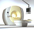
Device Information and Specification
CLINICAL APPLICATION
Whole body
CONFIGURATION
Short bore compact
Standard: head, body, C1, C3; Optional: Small joint, flex-E, flex-R, endocavitary (L and S), dual TMJ, knee, neck, T/L spine, breast; Optional phased array: Spine, pediatric, 3rd party connector, Optional SENSE Coils: Flex-S-M-L, Flex Body, Flex Cardiac
Optional
SYNCHRONIZATION
ECG/peripheral: Optional/yes, respiratory gating
PULSE SEQUENCES
SE, Modified-SE, IR (T1, T2, PD), STIR, FLAIR, SPIR, FFE, T1-FFE, T2-FFE, Balanced FFE, TFE, Balanced TFE, Dynamic, Keyhole, 3D, Multi Chunk 3D, Multi Stack 3D, K Space Shutter, MTC, TSE, Dual IR, DRIVE, EPI, Cine, 2DMSS, DAVE, Mixed Mode; Angiography: Inflow MRA, TONE, PCA, CE MRA
IMAGING MODES
Single Slice 2D , Multi Single Slice 2D, Multi Slice 2D, 3D, Multi Chunk 3D, Multi Stack 3D
TR
Min. 2.9 (Omni) msec, 1.6 (Power) msec
TE
Min. 1.0 (Omni) msec, 0.7 (Power) msec
SINGLE/MULTI SLICE
RapidView Recon. greater than 500 @ 256 Matrix
FOV
Max. 53 cm
0.1 mm(Omni), 0.05 mm (Power)
128 x 128, 256 x 256,512 x 512,1024 x 1024 (64 for Bold img)
MEASURING MATRIX
Variable in 1% increments
PIXEL INTENSITY
Lum.: 120 cd/m2; contrast: 150:1
Variable (op. param. depend.)
60 x 60 cm
MAGNET WEIGHT
2700 kg
H*W*D
240 x 188 x 157 cm
POWER REQUIREMENTS
380/400 V
CRYOGEN USE
0.03 L/hr helium
STRENGTH
23 mT/m (Omni), 30 (Power) mT/m
5-GAUSS FRINGE FIELD
2.3 m / 3.3 m
Passive and dynamic
spacer

• View the DATABASE results for 'Intera 1.0T™' (2).Open this link in a new window

MRI Resources 
Case Studies - Service and Support - Libraries - Crystallography - Societies - Portals
 
Pulse Sequence Timing DiagramInfoSheet: - Sequences - 
Intro, 
Overview, 
Types of, 
etc.
 
Spin Echo Timing Diagram The schematic figures of a pulse sequence timing diagram illustrate the steps of basic hardware activity that are incorporated into a pulse sequence. Time during sequence execution is indicated along the horizontal axes. Each line belongs to a different hardware component. One line is needed for the radio frequency transmitter and also one for each gradient (Gs = slice selection gradient x, Gf = phase encoding gradient y, Gf = frequency encoding gradient z, also called readout gradient).
In picture 1, a timing diagram for a 2D pulse sequence is shown.
Slice selection and signal detection are repeated in duration, relative timing and amplitude, each time the sequence is repeated. A single phase encoding component is present each time the sequence is executed.
Additional lines are added for ADC (Analog to Digital Converter) and sampling. A gradient pulse is shown as a deviation above or below the horizontal line. Simultaneous component activities such as the RF pulse and slice selection gradient are indicated as a non-zero deviation from both lines at the same horizontal position. Simple deviations from zero show constant amplitude gradient pulse. Gradient amplitudes that change during the measurement, e.g. phase encoding are represented as hatched regions.

Spin Echo Timing Diagram The second picture shows a timing diagram for a 3D pulse sequence.
Volume excitation and signal detection are repeated in duration, relative timing and amplitude, each time the sequence is repeated. Two phase encoding components are present, one in the phase encoding direction and the other in slice selection direction (irrespectively incremented in amplitude) in each time the sequence is executed. A description of the comparison of hardware activity between different pulse sequences.
spacer

• View the DATABASE results for 'Pulse Sequence Timing Diagram' (7).Open this link in a new window

MRI Resources 
MR Guided Interventions - Contrast Enhanced MRI - Safety pool - Knee MRI - Examinations - Case Studies
 
Chemical Shift ArtifactInfoSheet: - Artifacts - 
Case Studies, 
Reduction Index, 
etc.MRI Resource Directory:
 - Artifacts -
 
Quick Overview
Please note that there are different common names for this artifact.
Artifact Information
NAME
Chemical shift, black boundary, spatial misregistration, relief
DESCRIPTION
Black or bright band
During frequency encoding, fat protons precess slower than water protons in the same slice because of their magnetic shielding. Through the difference in resonance frequency between water and fat, protons at the same location are misregistrated (dislocated) by the Fourier transformation, when converting MRI signals from frequency to spatial domain. This chemical shift misregistration cause accentuation of any fat-water interfaces along the frequency axis and may be mistaken for pathology. Where fat and water are in the same location, this artifact can be seen as a bright or dark band at the edge of the anatomy.
Protons in fat and water molecules are separated by a chemical shift of about 3.5 ppm. The actual shift in Hertz (Hz) depends on the magnetic field strength of the magnet being used. Higher field strength increases the misregistration, while in contrast a higher gradient strength has a positive effect. For a 0.3 T system operating at 12.8 MHz the shift will be 44.8 Hz compared with a 223.6 Hz shift for a 1.5 T system operating at 63.9 MHz.
mri safety guidance
Image Guidance
For artifact reduction helps a smaller water fat shift (higher bandwidth), a higher matrix, an in phase TE or a spin echo technique. Since the misregistration offset is present in the read out axis the patient may be rescanned with this axis parallel to the fat-water interface. Steeper gradient may be employed to reduce the chemical shift offset in mm. Another strategy is to employ specialized pulse sequences such as fat saturation or inversion recovery imaging. Fat suppression techniques eliminate chemical shift artifacts caused by the lack of fat signal.

See also Black Boundary Artifact and Magnetic Resonance Spectroscopy.
spacer

• View the DATABASE results for 'Chemical Shift Artifact' (7).Open this link in a new window

 
Further Reading:
  Basics:
MRI Artifact Gallery
   by chickscope.beckman.uiuc.edu    
  News & More:
What is chemical shift artefact? Why does it occur? How many Hz at 1.5 T?
   by www.revisemri.com    
Abdominal MRI at 3.0 T: The Basics Revisited
Wednesday, 20 July 2005   by www.ajronline.org    
MRI Resources 
Libraries - Safety pool - Anatomy - Developers - MRI Physics - Bioinformatics
 
     1 - 5 (of 20)     next
Result Pages : [1]  [2 3 4]
 Random Page
 
Share This Page
FacebookTwitterLinkedIn

MR-TIP    
Community   
User
Pass
Forgot your UserID/Password ?    


Next big thing in MRI will be :
AI 
remote operator 
personalized protocols 
helium-free 
molecular MRI 
portable MRI 

Look
      Ups


MR-TIP.com uses cookies! By browsing MR-TIP.com, you agree to our use of cookies.

Magnetic Resonance - Technology Information Portal
Member of SoftWays' Medical Imaging Group - MR-TIP • Radiology-TIP • Medical-Ultrasound-Imaging • 
Copyright © 2003 - 2024 SoftWays. All rights reserved. [ 19 April 2024]
Terms of Use | Privacy Policy | Advertising
 [last update: 2024-02-26 03:41:00]