 | Info
Sheets |
| | | | | | | | | | | | | | | | | | | | | | | | |
 | Out-
side |
| | | | |
|
| | | | | |  | Searchterm 'Second' was also found in the following services: | | | | |
|  |  |
| |
|
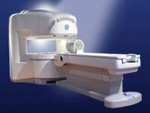
From GE Healthcare;
the Signa Ovation™ is a patient-friendly open MRI scanner designed not only to handle a typical patient mix, but to accommodate larger patients, patients who are claustrophobic, and others who have difficulty tolerating the close quarters of conventional MR machines.
Device Information and Specification CLINICAL APPLICATION Whole body Standard: SE, IR, 2D/3D GRE and SPGR, 2D/3D TOF, 2D/3D FSE, 2D/3D FGRE and FSPGR, SSFP, FLAIR, EPI, optional: 2D/3D Fiesta, true chem sat, fat/water separation, single shot diffusion EPI, line scan diffusionIMAGING MODES Localizer, single slice, multislice, volume, fast, POMP, multi slab, cine, slice and frequency zip, extended dynamic range, tailored RF TR 1.3 to 12000 msec in increments of 1 msec TE 0.4 to 2000 msec in increments of 1 msec 2D: 1.4mm - 20mm 3D: 0.2mm - 20mm 0.08 mm; 0.02 mm optional POWER REQUIREMENTS 200 - 480, 3-phase MAX. GRADIENT AMPLITUDE 19 mT/m | | | | | |
| | | Searchterm 'Second' was also found in the following services: | | | | |
| | |
| |
|
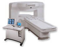
From GE Healthcare;
the New Signa Profile/i is a patient friendly open MRI system that virtually eliminates patient anxiety and claustrophobia, without compromising diagnostic utility.
Device Information and Specification CLINICAL APPLICATION Whole body Integrated transmit body coil, body flex sizes: M, L, XL, quadrature, head coil quadrature, 4 channel neurovascular array, 8 channel CTL array, quad. c- spine, 2 channel shoulder array, extremity coil, 3 channel wrist array, 4 channel breast array, 6, 9, 11 inch general purpose loop coils Standard: SE, IR, 2D/3D GRE and SPGR, Angiography: 2D/3D TOF, 2D/3D phase contrast; 2D/3D FSE, 2D/3D FRFSE, FGRE and FSPGR, SSFP, FLAIR, EPI, optional: 2D/3D Fiesta, fat/water separation, T1 FLAIRIMAGING MODES Localizer, single slice, multislice, volume, fast, POMP, multi slab, cine, slice and frequency zip, extended dynamic range, tailored RF TR 6 to 12000 msec in increments of 1 msec TE 1.3 to 2000 msec in increments of 1 msec 2D: 2.7mm - 20mm 3D: 0.2mm - 5mm 0.08 mm; 0.02 mm optional 10,000 kg w/gradient enclosure POWER REQUIREMENTS 200 - 480, 3-phase COOLING SYSTEM TYPE None required | | | |
• View the DATABASE results for 'Signa Profile™' (2).
| | | | |
| | | | | |
| |
|
Exited measurement volume for 3D imaging. Slices are defined by a second phase encoded axis, which divides the volume into partitions without a gap. | | | |
• View the DATABASE results for 'Slab' (28).
| | | | |
| | | Searchterm 'Second' was also found in the following services: | | | | |
| | |
| |
|
(SAR) The Specific Absorption Rate is defined as the RF power absorbed per unit of mass of an object, and is measured in watts per kilogram (W/kg).
The SAR describes the potential for heating of the patient's tissue due to the application of the RF energy necessary to produce the MR signal. Inhomogeneity of the RF field leads to a local exposure where most of the absorbed energy is applied to one body region rather than the entire person, leading to the concept of a local SAR. Hot spots may occur in the exposed tissue, to avoid or at least minimize effects of such theoretical complications, the frequency and the power of the radio frequency irradiation should be kept at the lowest possible level. Averaging over the whole body leads to the global SAR.
It increases with field strength, radio frequency power and duty cycle, transmitter-coil type and body size. The doubling of the field strength from 1.5 Tesla (1.5T) to 3 Tesla ( 3T) leads to a quadrupling of SAR. In high and ultrahigh fields, some of the multiple echo, multiple-slice pulse sequences may create a higher SAR than recommended by the agencies. SAR can be reduced by lower flip angle and longer repetition times, which could potentially affect image contrast.
Normally no threatening increase in temperature could be shown. Even in high magnetic fields, the local temperature increases not more than 1°C. 2.1°C is the highest measured increase in skin temperature. Eddy currents may heat up implants and thus may cause local heating.
FDA SAR limits:
•
Whole body: 4W/kg/15-minute exposure averaged;
•
Head: 3W/kg/10-minute exposure averaged;
•
Head or torso: 8W/kg/5 minute exposure per gram of tissue;
•
Extremities: 12W/kg/5 minute exposure per gram of tissue.
IEC (International Electrotechnical Commission) SAR limits of some European countries:
All limits are averaged over 6 minutes.
•
Level 0 (normal operating mode): Whole body 2W/kg; Head 3.2W/kg; Head or Torso (local) 10W/kg;
Extremities (local) 20W/kg;
•
Level I (first level controlled operating mode): Whole body 4W/kg; Head 3.2W/kg; Head or Torso (local) 10W/kg; Extremities (local) 20W/kg;
•
Level II (second level controlled operating mode): All values are over Level I values.
(For more details: IEC 60601-2-33 (2002))
In most countries standard MRI systems are limited to a maximum SAR of 4 W/kg, so most scanning in level II is impossible.
For Level I, in addition to routine monitoring, particular caution must be exercised for patients who are sensitive to temperature increases or to RF energy.
For Japan different SAR limits are valid. | | | |
• View the DATABASE results for 'Specific Absorption Rate' (8).
| | |
• View the NEWS results for 'Specific Absorption Rate' (1).
| | | | |  Further Reading: Further Reading: | | Basics:
|
|
News & More:
| |
| |
| | | Searchterm 'Second' was also found in the following services: | | | | |
| | |
| |
|
Superconducting magnets are electromagnets that are partially built from
superconducting materials and therefore reach much higher magnetic field intensity.
The coil windings of superconducting magnets are made of wires of a type 2 superconductor (mostly used is niobium-titanium - up to 15 Tesla the critical temperature is less then 10 Kelvin). These coils have no resistance when operated at temperatures near absolute zero (-273.15°C, -459°F, 0 K).
Liquid helium (4.2 K) is commonly used as a coolant (sometimes in addition with a second cryogen liquid nitrogen as an intermediate thermal shield to reduce the boil-off rate of liquid helium), which consequently conclude refilling (intervals: liquid helium ~ 3 month, liquid nitrogen ~ 2 weeks). There are cryogen-free superconducting magnets with a closed-cycle refrigerating system at the horizon. Superconducting magnets typically exhibit field strengths of greater than 0.5 T, operate clinically up to 3 T, and have a horizontal field orientation, which makes them prone to missile effects without significant magnetic shielding.
See also Quenching.
See also the related poll result: ' In 2010 your scanner will probably work with a field strength of' | | | |
• View the DATABASE results for 'Superconducting Magnet' (15).
| | |
• View the NEWS results for 'Superconducting Magnet' (3).
| | | | | | Further Reading: | | Basics:
|
|
News & More:
| |
| |
| | | | |
| | | |
|
| |
 | Look
Ups |
| |


