Magnetic Resonance - Technology Information Portal Welcome to MRI Technology
Info
  Sheets

Out-
      side


 'Relaxation Time' 
SEARCH FOR    
 
  2 3 5 A B C D E F G H I J K L M N O P Q R S T U V W X Y Z
Result : Searchterm 'Relaxation Time' found in 5 terms [] and 52 definitions []
previous     11 - 15 (of 57)     next
Result Pages : [1]  [2 3 4 5 6 7 8 9 10 11 12]
Searchterm 'Relaxation Time' was also found in the following services: 
spacer
News  (3)  Resources  (2)  Forum  (6)  
 
Inversion Recovery SequenceForum -
related threadsInfoSheet: - Sequences - 
Intro, 
Overview, 
Types of, 
etc.
 
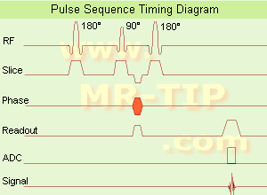
Inversion Recovery Sequence Timing Diagram (IR) The inversion recovery pulse sequence produces signals, which represent the longitudinal magnetization existing after the application of a 180° radio frequency pulse that rotates the magnetization Mz into the negative plane. After an inversion time (TI - time between the starting 180° pulse and the following 90° pulse), a further 90° RF pulse tilts some or all of the z-magnetization into the xy-plane, where the signal is usually rephased with a 180° pulse as in the spin echo sequence. During the initial time period, various tissues relax with their intrinsic T1 relaxation time.
In the pulse sequence timing diagram, the basic inversion recovery sequence is illustrated. The 180° inversion pulse is attached prior to the 90° excitation pulse of a spin echo acquisition. See also the Pulse Sequence Timing Diagram. There you will find a description of the components.
The inversion recovery sequence has the advantage, that it can provide very strong contrast between tissues having different T1 relaxation times or to suppress tissues like fluid or fat. But the disadvantage is, that the additional inversion radio frequency RF pulse makes this sequence less time efficient than the other pulse sequences.

Contrast values:
PD weighted: TE: 10-20 ms, TR: 2000 ms, TI: 1800 ms
T1 weighted: TE: 10-20 ms, TR: 2000 ms, TI: 400-800 ms
T2 weighted: TE: 70 ms, TR: 2000 ms, TI: 400-800 ms

See also Inversion Recovery, Short T1 Inversion Recovery, Fluid Attenuation Inversion Recovery, and Acronyms for 'Inversion Recovery Sequence' from different manufacturers.
 
Images, Movies, Sliders:
 Brain MRI Inversion Recovery  Open this link in a new window
    
 Knee MRI Sagittal STIR 002  Open this link in a new window
 Brain MRI Coronal FLAIR 001  Open this link in a new window
    
 
spacer
 
• Related Searches:
    • Pulse Sequence Timing Diagram
    • Brain MRI
    • Saturation Pulses
    • Flow Sensitive Alternating Inversion Recovery
    • Pulse, 180°
 
Further Reading:
  Basics:
The equation for a repeated inversion recovery sequence
Contrast mechanisms in magnetic resonance imaging
2004   by www.iop.org    
  News & More:
FLAIR Vascular Hyperintensity: An Important MRI Marker in Patients with Transient Ischemic Attack
Thursday, 14 July 2022   by www.dovepress.com    
MRI Resources 
Brain MRI - Functional MRI - Breast MRI - Safety pool - Portals - Distributors
 
Magnetization Transfer
 
(MT) Magnetization Transfer was accidentally discovered by Wolff and Balaban in 1989. Conventional MRI is based on the differences in T1, T2 and the proton density (water content and the mobility of water molecules) in tissue; it relies primarily on free (bulk) water protons. The T2 relaxation times are greater than 10 ms and detectable. The T2 relaxation times of protons associated with macromolecules are less then 1 ms and not detectable in MRI.
Magnetization Transfer Imaging (MTI) is based on the magnetization interaction (through dipolar and/or chemical exchange) between bulk water protons and macromolecular protons. By applying an off resonance radio frequency pulse to the macromolecular protons, the saturation of these protons is then transferred to the bulk water protons. The result is a decrease in signal (the net magnetization of visible protons is reduced), depending on the magnitude of MT between tissue macromolecules and bulk water. With MTI, the presence or absence of macromolecules (e.g. in membranes, brain tissue) can be seen.
The magnetization transfer ratio (MTR) is the difference in signal intensity with or without MT.

See also Magnetization Transfer Contrast.
spacer

• View the DATABASE results for 'Magnetization Transfer' (7).Open this link in a new window

 
Further Reading:
  Basics:
MICRO-STRUCTURAL QUANTITIES - DIFFUSION, MAGNETISATION DECAY, MAGNETISATION TRANSFER AND PERMEABILITY(.pdf)
   by www.dundee.ac.uk    
The Basics of MRI
   by www.cis.rit.edu    
  News & More:
Gold-manganese nanoparticles for targeted diagnostic and imaging
Thursday, 12 November 2015   by www.nanowerk.com    
Magnetization Transfer Magnetic Resonance Imaging of Hepatic Tumors(.pdf)
   by www.nci.edu.eg    
MRI Resources 
Case Studies - Services and Supplies - Libraries - Mobile MRI Rental - Pathology - MRA
 
Partial SaturationInfoSheet: - Sequences - 
Intro, 
Overview, 
Types of, 
etc.
 
(PS) Excitation technique applying repeated RF pulses in times comparable to or shorter than T1. Incomplete T1 relaxation leads to reduction of the signal amplitude; there is the possibility of generating images with increased contrast between regions with different relaxation times.
Although partial saturation is also commonly referred to as saturation recovery, that term should properly be reserved for the particular case of partial saturation in which recovery after each excitation effectively takes place from true saturation. A GRE sequence where α = 90° is identical to the partial saturation or saturation recovery pulse sequence.
It does not directly produce images of T1. However, since the measured signal will depend on T1, the method generates contrast between regions with different relaxation times. If T2 and/or T2 effects are minimized through the use of a short echo time TE, the result is a T1 weighted image. It is not a T1 image due to the possible presence of spin density and T2 effects as well as the nonlinear dependence on T1.
The change in signal from a region resulting from a change in the interpulse time, TR, can be used to calculate T1 for the region.
spacer

• View the DATABASE results for 'Partial Saturation' (5).Open this link in a new window

Searchterm 'Relaxation Time' was also found in the following services: 
spacer
News  (3)  Resources  (2)  Forum  (6)  
 
Relaxation Rates
 
Reciprocals of the relaxation times, T1 and T2 (R1 = 1/T1 and R2 = 1/T2). There is often a linear relation between the concentration of MR contrast agents and the resulting change in relaxation rate. The rate of relaxation is influenced by molecules with protons that are tumbling. A slower tumble rate will result in faster relaxation rate (shorter relaxation time). Due to the molecular structure of fat with its larger size than water, fat will tumble slower than water molecules. The slower tumble rate of fat enables a faster relaxation rate.
spacer

• View the DATABASE results for 'Relaxation Rates' (5).Open this link in a new window

 
Further Reading:
  Basics:
Evaluation of Absorbed Dose by MRI Read-Out
Saturday, 18 November 2017   by www.jstage.jst.go.jp    
  News & More:
Multimodal Nanoparticles for Quantitative Imaging(.pdf)
Tuesday, 13 December 2011   by alexandria.tue.nl    
MRI Resources 
Shoulder MRI - MRI Technician and Technologist Career - - Pediatric and Fetal MRI - Quality Advice - MRI Technician and Technologist Jobs
 
Relaxometry
 
Relaxation time is a general physics concept for the characteristic time in which a system relaxes under certain changes in external conditions. Relaxometry is the theory of relaxation times (spin lattice (T1) and spin spin relaxation (T2)), and their dependence on physical parameters such as magnetic field strength, molecular structure, temperature, pH, and the presence and type of relaxation agents.
spacer

• View the NEWS results for 'Relaxometry' (1).Open this link in a new window.
 
Further Reading:
  Basics:
Measurements of the relaxivity of gadolinium chelates in tissues in vivo(.pdf)
2001   by cds.ismrm.org    
  News & More:
Imagion (ASX:IBX) share price up 1,166% in a year pursuing adiation-freeâ„¢ cancer tech
Monday, 29 March 2021   by www.fool.com.au    
MRI Resources 
Pathology - Software - Raman Spectroscopy - MRI Reimbursement - Lung Imaging - Spine MRI
 
previous      11 - 15 (of 57)     next
Result Pages : [1]  [2 3 4 5 6 7 8 9 10 11 12]
 Random Page
 
Share This Page
FacebookTwitterLinkedIn

MR-TIP    
Community   
User
Pass
Forgot your UserID/Password ?    


New acceleration techniques will :
reduce scan times 
cause artifacts 
increase expenses 
be useful if you have a lot of experience 
doesn't do much 
never heard of 

Look
      Ups


MR-TIP.com uses cookies! By browsing MR-TIP.com, you agree to our use of cookies.

Magnetic Resonance - Technology Information Portal
Member of SoftWays' Medical Imaging Group - MR-TIP • Radiology-TIP • Medical-Ultrasound-Imaging • 
Copyright © 2003 - 2024 SoftWays. All rights reserved. [ 19 April 2024]
Terms of Use | Privacy Policy | Advertising
 [last update: 2024-02-26 03:41:00]