 | Info
Sheets |
| | | | | | | | | | | | | | | | | | | | | | | | |
 | Out-
side |
| | | | |
|
| | | | |
Result : Searchterm 'Radio Frequency' found in 12 terms [ ] and 63 definitions [ ] and 63 definitions [ ] ]
| | previous 16 - 20 (of 75) nextResult Pages : [1 2 3] [4 5 6 7 8 9 10 11 12 13 14 15] |  | |  | Searchterm 'Radio Frequency' was also found in the following services: | | | | |
| |  |
| |
|
Magnetic resonance imaging ( MRI) is based on the magnetic resonance phenomenon, and is used for medical diagnostic imaging since ca. 1977 (see also MRI History).
The first developed MRI devices were constructed as long narrow tunnels. In the meantime the magnets became shorter and wider. In addition to this short bore magnet design, open MRI machines were created. MRI machines with open design have commonly either horizontal or vertical opposite installed magnets and obtain more space and air around the patient during the MRI test.
The basic hardware components of all MRI systems are the magnet, producing a stable and very intense magnetic field, the gradient coils, creating a variable field and radio frequency (RF) coils which are used to transmit energy and to encode spatial positioning. A computer controls the MRI scanning operation and processes the information.
The range of used field strengths for medical imaging is from 0.15 to 3 T. The open MRI magnets have usually field strength in the range 0.2 Tesla to 0.35 Tesla. The higher field MRI devices are commonly solenoid with short bore superconducting magnets, which provide homogeneous fields of high stability.
There are this different types of magnets:
The majority of superconductive magnets are based on niobium-titanium (NbTi) alloys, which are very reliable and require extremely uniform fields and extreme stability over time, but require a liquid helium cryogenic system to keep the conductors at approximately 4.2 Kelvin (-268.8° Celsius). To maintain this temperature the magnet is enclosed and cooled by a cryogen containing liquid helium (sometimes also nitrogen).
The gradient coils are required to produce a linear variation in field along one direction, and to have high efficiency, low inductance and low resistance, in order to minimize the current requirements and heat deposition. A Maxwell coil usually produces linear variation in field along the z-axis; in the other two axes it is best done using a saddle coil, such as the Golay coil.
The radio frequency coils used to excite the nuclei fall into two main categories; surface coils and volume coils.
The essential element for spatial encoding, the gradient coil sub-system of the MRI scanner is responsible for the encoding of specialized contrast such as flow information, diffusion information, and modulation of magnetization for spatial tagging.
An analog to digital converter turns the nuclear magnetic resonance signal to a digital signal. The digital signal is then sent to an image processor for Fourier transformation and the image of the MRI scan is displayed on a monitor.
For Ultrasound Imaging (USI) see Ultrasound Machine at Medical-Ultrasound-Imaging.com.
See also the related poll results: ' In 2010 your scanner will probably work with a field strength of' and ' Most outages of your scanning system are caused by failure of' | | | | | | | | | | | | | | | |  Further Reading: Further Reading: | News & More:
|
 |
small-steps-can-yield-big-energy-savings-and-cut-emissions-mris
Thursday, 27 April 2023 by www.itnonline.com | | |
Portable MRI can detect brain abnormalities at bedside
Tuesday, 8 September 2020 by news.yale.edu | | |
Point-of-Care MRI Secures FDA 510(k) Clearance
Thursday, 30 April 2020 by www.diagnosticimaging.com | | |
World's First Portable MRI Cleared by FDA
Monday, 17 February 2020 by www.medgadget.com | | |
Low Power MRI Helps Image Lungs, Brings Costs Down
Thursday, 10 October 2019 by www.medgadget.com | | |
Cheap, portable scanners could transform brain imaging. But how will scientists deliver the data?
Tuesday, 16 April 2019 by www.sciencemag.org | | |
The world's strongest MRI machines are pushing human imaging to new limits
Wednesday, 31 October 2018 by www.nature.com | | |
Kyoto University and Canon reduce cost of MRI scanner to one tenth
Monday, 11 January 2016 by www.electronicsweekly.com | | |
A transportable MRI machine to speed up the diagnosis and treatment of stroke patients
Wednesday, 22 April 2015 by medicalxpress.com | | |
Portable 'battlefield MRI' comes out of the lab
Thursday, 30 April 2015 by physicsworld.com | | |
Chemists develop MRI technique for peeking inside battery-like devices
Friday, 1 August 2014 by www.eurekalert.org | | |
New devices doubles down to detect and map brain signals
Monday, 23 July 2012 by scienceblog.com |
|
| |
| | | Searchterm 'Radio Frequency' was also found in the following service: | | | | |
| | |
| |
|
Duty cycle is the time during which the gradient system can be run at maximum power. The duty cycle is based on the total time and includes the cool down phase. The duty cycle on the RF pulse during MRI is restricted based on the specific absorption rate (SAR) limit. SAR limits restrict radio frequency heating effects. The specific absorption rate increases with field strength, radio frequency power and duty cycle, type of the transmitter coil and body size. The especially in high and ultrahigh magnetic fields, important SAR issue can be readily addressed by reducing the RF duty cycle due to longer repetition times (TR) and the use of parallel imaging techniques. A TR longer than the minimum needed provides time for the tissue to cool down, but for the cost of a longer scan time. A parallel imaging technique reduces the RF exposure and the scan time. See also High Field MRI. | | | |
• View the DATABASE results for 'Duty Cycle' (5).
| | | | |
| | | | | |
| |
|
(IR) The inversion recovery pulse sequence produces signals, which represent the longitudinal magnetization existing after the application of a 180° radio frequency pulse that rotates the magnetization Mz into the negative plane. After an inversion time (TI - time between the starting 180° pulse and the following 90° pulse), a further 90° RF pulse tilts some or all of the z-magnetization into the xy-plane, where the signal is usually rephased with a 180° pulse as in the spin echo sequence. During the initial time period, various tissues relax with their intrinsic T1 relaxation time.
In the pulse sequence timing diagram, the basic inversion recovery sequence is illustrated. The 180° inversion pulse is attached prior to the 90° excitation pulse of a spin echo acquisition.
See also the Pulse Sequence Timing Diagram. There you will find a description of the components.
The inversion recovery sequence has the advantage, that it can provide very strong contrast between tissues having different T1 relaxation times or to suppress tissues like fluid or fat.
But the disadvantage is, that the additional inversion radio frequency RF pulse makes this sequence less time efficient than the other pulse sequences.
Contrast values:
PD weighted: TE: 10-20 ms, TR: 2000 ms, TI: 1800 ms
T1 weighted: TE: 10-20 ms, TR: 2000 ms, TI: 400-800 ms
T2 weighted: TE: 70 ms, TR: 2000 ms, TI: 400-800 ms
See also Inversion Recovery, Short T1 Inversion Recovery, Fluid Attenuation Inversion Recovery, and Acronyms for 'Inversion Recovery Sequence' from different manufacturers. | | | | | |
• View the DATABASE results for 'Inversion Recovery Sequence' (8).
| | | | | | Further Reading: | | Basics:
|
|
News & More:
| |
| |
| | | Searchterm 'Radio Frequency' was also found in the following services: | | | | |
| | |
| |
|
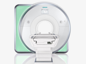
From Siemens Medical Systems;
Received FDA clearance in 2010.
The MAGNETOM Aera is a patient friendly, comfortable 1.5 Tesla MRI system with advanced radio frequency chain.
The system is equipped with the Tim 4G and Dot system (Total imaging matrix + Day optimizing throughput), to enhance both productivity and image quality.
Tim 4G technology provides improved SNR. The standard system configuration of 48 radio frequency channels and 204 coil elements creates an imaging matrix that allows maximum use of coil elements at full field of view. Dot provides improved image consistency through new features like auto align, auto FoV and automatic bolus detection.
Device Information and Specification
CLINICAL APPLICATION
Whole body
Head, spine, torso/ body coil, neurovascular, cardiac, neck, shoulder, knee, wrist, foot//ankle and multi-purpose flex coils. Peripheral vascular, breast, shoulder. Up to 60% more SNR with Tim 4G.
CHANNELS (min. / max. configuration)
48, 64
MINIMUM TE
3-D GRE: 0.22 (256 matrix), Ultra-short TE
At isocenter: L-R 70 cm, A-P (with table) 55 cm
MAGNET WEIGHT (gantry included)
3121 kg
DIMENSION H*W*D (gantry included)
145 x 231 x 219 cm
MAX. AMPLITUDE
33 or 45 mT/m
3 linear with 20 coils, 5 nonlinear 2nd-order
POWER REQUIREMENTS
380 / 400 / 420 / 440 / 460 / 480 V, 3-phase + ground; 85 kVA
| | | | | |
| | | Searchterm 'Radio Frequency' was also found in the following service: | | | | |
| | |
| |
|

It is important to remember when working around a superconducting magnet that the magnetic field is always on. Under usual working conditions the field is never turned off. Attention must be paid to keep all ferromagnetic items at an adequate distance from the magnet. Ferromagnetic objects which came accidentally under the influence of these strong magnets can injure or kill individuals in or nearby the magnet, or can seriously damage every hardware, the magnet itself, the cooling system, etc..
See MRI resources Accidents.
The doors leading to a magnet room should be closed at all times except when entering or exiting the room. Every person working in or entering the magnet room or adjacent rooms with a magnetic field has to be instructed about the dangers. This should include the patient, intensive-care staff, and maintenance-, service- and cleaning personnel, etc..
The 5 Gauss limit defines the 'safe' level of static magnetic field exposure. The value of the absorbed dose is fixed by the authorities to avoid heating of the patient's tissue and is defined by the specific absorption rate.
Leads or wires that are used in the magnet bore during imaging procedures, should not form large-radius wire loops. Leg-to-leg and leg-to-arm skin contact should be prevented in order to avoid the risk of burning due to the generation of high current loops if the legs or arms are allowed to touch. The patient's skin should not be in contact with the inner bore of the magnet.
The outflow from cryogens like liquid helium is improbable during normal operation and not a real danger for patients.
The safety of MRI contrast agents is tested in drug trials and they have a high compatibility with very few side effects. The variations of the side effects and possible contraindications are similar to X-ray contrast medium, but very rare. In general, an adverse reaction increases with the quantity of the MRI contrast medium and also with the osmolarity of the compound.
See also 5 Gauss Fringe Field, 5 Gauss Line, Cardiac Risks, Cardiac Stent, dB/dt, Legal Requirements, Low Field MRI, Magnetohydrodynamic Effect, MR Compatibility, MR Guided Interventions, Claustrophobia, MRI Risks and Shielding. | | | | | | | | |
• View the DATABASE results for 'MRI Safety' (42).
| | |
• View the NEWS results for 'MRI Safety' (13).
| | | | | | Further Reading: | Basics:
|
|
News & More:
| |
| |
| | | | |
| | | |
|
| |
 | Look
Ups |
| |


