Magnetic Resonance - Technology Information Portal Welcome to MRI Technology
Info
  Sheets

Out-
      side


 'Longitudinal Relaxation Rate' 
SEARCH FOR    
 
  2 3 5 A B C D E F G H I J K L M N O P Q R S T U V W X Y Z
Result : Searchterm 'Longitudinal Relaxation Rate' found in 1 term [] and 2 definitions [], (+ 7 Boolean[] results
1 - 5 (of 10)     next
Result Pages : [1]  [2]
MRI Resources 
Movies - Pregnancy - Quality Advice - MRI Technician and Technologist Jobs - Intraoperative MRI - Supplies
 
Longitudinal Relaxation Rate
 
(R1/R2) The longitudinal relaxation rate is equal to reciprocal of relaxation time.
spacer
 
• Share the entry 'Longitudinal Relaxation Rate':  Facebook  Twitter  LinkedIn  
 
Further Reading:
  Basics:
Measuring T1 and T2 Relaxation - Introductory NMR & MRI from Magritek
   by www.azom.com    
MRI Resources 
Diffusion Weighted Imaging - Absorption and Emission - Raman Spectroscopy - Shielding - NMR - MRA
 
R1
 
Longitudinal relaxation rate equal to reciprocal of T1 relaxation time (R1= 1/T1).
spacer

• View the DATABASE results for 'R1' (33).Open this link in a new window

MRI Resources 
Veterinary MRI - Used and Refurbished MRI Equipment - Spectroscopy - Case Studies - MRI Training Courses - Safety pool
 
R2
 
Longitudinal relaxation rate equal to reciprocal of T2 relaxation time (R2 = 1/T2).
spacer

• View the DATABASE results for 'R2' (26).Open this link in a new window


• View the NEWS results for 'R2' (1).Open this link in a new window.
MRI Resources 
Safety Training - Pacemaker - Process Analysis - Non-English - Distributors - MRCP
 
Spin Echo SequenceInfoSheet: - Sequences - 
Intro, 
Overview, 
Types of, 
etc.MRI Resource Directory:
 - Sequences -
 
Spin Echo Timing Diagram (SE) The most common pulse sequence used in MR imaging is based of the detection of a spin or Hahn echo. It uses 90° radio frequency pulses to excite the magnetization and one or more 180° pulses to refocus the spins to generate signal echoes named spin echoes (SE).
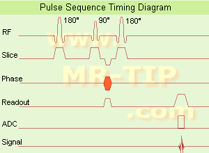
In the pulse sequence timing diagram, the simplest form of a spin echo sequence is illustrated.
The 90° excitation pulse rotates the longitudinal magnetization (Mz) into the xy-plane and the dephasing of the transverse magnetization (Mxy) starts.
The following application of a 180° refocusing pulse (rotates the magnetization in the x-plane) generates signal echoes. The purpose of the 180° pulse is to rephase the spins, causing them to regain coherence and thereby to recover transverse magnetization, producing a spin echo.
The recovery of the z-magnetization occurs with the T1 relaxation time and typically at a much slower rate than the T2-decay, because in general T1 is greater than T2 for living tissues and is in the range of 100-2000 ms.
The SE pulse sequence was devised in the early days of NMR days by Carr and Purcell and exists now in many forms: the multi echo pulse sequence using single or multislice acquisition, the fast spin echo (FSE/TSE) pulse sequence, echo planar imaging (EPI) pulse sequence and the gradient and spin echo (GRASE) pulse sequence;; all are basically spin echo sequences.
In the simplest form of SE imaging, the pulse sequence has to be repeated as many times as the image has lines.
Contrast values:
PD weighted: Short TE (20 ms) and long TR.
T1 weighted: Short TE (10-20 ms) and short TR (300-600 ms)
T2 weighted: Long TE (greater than 60 ms) and long TR (greater than 1600 ms)
With spin echo imaging no T2* occurs, caused by the 180° refocusing pulse. For this reason, spin echo sequences are more robust against e.g., susceptibility artifacts than gradient echo sequences.

See also Pulse Sequence Timing Diagram to find a description of the components.
 
Images, Movies, Sliders:
 Shoulder Coronal T1 SE  Open this link in a new window
    

Courtesy of  Robert R. Edelman
 Shoulder Axial T1 SE  Open this link in a new window
 MRI Orbita T1  Open this link in a new window
    
 
spacer

• View the DATABASE results for 'Spin Echo Sequence' (24).Open this link in a new window

 
Further Reading:
  Basics:
Fast Spin Echo(.pdf)
Tuesday, 24 January 2006   by www.81bones.net    
Magnetic resonance imaging
   by www.scholarpedia.org    
FUNDAMENTALS OF MRI: Part I
   by www.e-radiography.net    
  News & More:
New MR sequence helps radiologists more accurately evaluate abnormalities of the uterus and ovaries
Thursday, 23 April 2009   by www.eurekalert.org    
MRI techniques improve pulmonary embolism detection
Monday, 19 March 2012   by medicalxpress.com    
MRI Resources 
Corporations - Service and Support - Process Analysis - Liver Imaging - Societies - Brain MRI
 
Inversion Recovery SequenceForum -
related threadsInfoSheet: - Sequences - 
Intro, 
Overview, 
Types of, 
etc.
 
Inversion Recovery Sequence Timing Diagram (IR) The inversion recovery pulse sequence produces signals, which represent the longitudinal magnetization existing after the application of a 180° radio frequency pulse that rotates the magnetization Mz into the negative plane. After an inversion time (TI - time between the starting 180° pulse and the following 90° pulse), a further 90° RF pulse tilts some or all of the z-magnetization into the xy-plane, where the signal is usually rephased with a 180° pulse as in the spin echo sequence. During the initial time period, various tissues relax with their intrinsic T1 relaxation time.
In the pulse sequence timing diagram, the basic inversion recovery sequence is illustrated. The 180° inversion pulse is attached prior to the 90° excitation pulse of a spin echo acquisition. See also the Pulse Sequence Timing Diagram. There you will find a description of the components.
The inversion recovery sequence has the advantage, that it can provide very strong contrast between tissues having different T1 relaxation times or to suppress tissues like fluid or fat. But the disadvantage is, that the additional inversion radio frequency RF pulse makes this sequence less time efficient than the other pulse sequences.

Contrast values:
PD weighted: TE: 10-20 ms, TR: 2000 ms, TI: 1800 ms
T1 weighted: TE: 10-20 ms, TR: 2000 ms, TI: 400-800 ms
T2 weighted: TE: 70 ms, TR: 2000 ms, TI: 400-800 ms

See also Inversion Recovery, Short T1 Inversion Recovery, Fluid Attenuation Inversion Recovery, and Acronyms for 'Inversion Recovery Sequence' from different manufacturers.
 
Images, Movies, Sliders:
 Brain MRI Inversion Recovery  Open this link in a new window
    
 Knee MRI Sagittal STIR 002  Open this link in a new window
 Brain MRI Coronal FLAIR 001  Open this link in a new window
    
 
spacer

• View the DATABASE results for 'Inversion Recovery Sequence' (8).Open this link in a new window

 
Further Reading:
  Basics:
The equation for a repeated inversion recovery sequence
Contrast mechanisms in magnetic resonance imaging
2004   by www.iop.org    
  News & More:
FLAIR Vascular Hyperintensity: An Important MRI Marker in Patients with Transient Ischemic Attack
Thursday, 14 July 2022   by www.dovepress.com    
MRI Resources 
Spine MRI - MRI Reimbursement - MR Myelography - Spectroscopy - MRI Technician and Technologist Schools - Homepages
 
     1 - 5 (of 10)     next
Result Pages : [1]  [2]
 Random Page
 
Share This Page
FacebookTwitterLinkedIn

MR-TIP    
Community   
User
Pass
Forgot your UserID/Password ?    


How AI will impact MRI :
only diagnostics 
saving time 
reducing cost 
makes planning obsolete 
reduce human knowledge 
not at all 

Look
      Ups


MR-TIP.com uses cookies! By browsing MR-TIP.com, you agree to our use of cookies.

Magnetic Resonance - Technology Information Portal
Member of SoftWays' Medical Imaging Group - MR-TIP • Radiology-TIP • Medical-Ultrasound-Imaging • 
Copyright © 2003 - 2024 SoftWays. All rights reserved. [ 25 April 2024]
Terms of Use | Privacy Policy | Advertising
 [last update: 2024-02-26 03:41:00]