 | Info
Sheets |
| | | | | | | | | | | | | | | | | | | | | | | | |
 | Out-
side |
| | | | |
|
| | | | |
Result : Searchterm 'Image Quality' found in 1 term [ ] and 44 definitions [ ] and 44 definitions [ ] ]
| | previous 31 - 35 (of 45) nextResult Pages : [1] [2 3 4 5 6 7 8 9] |  | |  | Searchterm 'Image Quality' was also found in the following services: | | | | |
| |  |
| |
|
The multi angle oblique technique gives the ability to display anatomical structures in a variety of planes from the data acquired in just one MRI scan.
This technique is useful, for example in lumbar spine MRI obtaining images of each intervertebral disc, individually oriented at a different angle, to better recognize herniation or to compare degenerative changes.
This technique is more difficult in the cervical spine MRI region because of the small vertebra and therefore a short distance between the multi angle oblique planes. In case of too short distance or overlapping slices the crosstalk (artifact) destroys the signal with reduced image quality. | | | | | |
| | | Searchterm 'Image Quality' was also found in the following services: | | | | |
| | | | | | | |
| |
|
An undesirable background interference or disturbance that affects image quality.
The Noise is commonly characterized by the standard deviation of signal intensity in the image of a uniform object ( phantom) in the absence of artifacts. The measured noise may depend on the particular phantom used due to variable effects on the Q of the receiver coil. Noisy images appear when the SNR-Rate is too low - this is induced by the operator.
Image artifacts and RF noise can often be caused by the presence and/or operation of a medical device in the MR environment.
There are various noise sources in any electronic system, including Johnson noise, shot noise, thermal noise. Materials produce their own characteristic static magnetic field that can perturb the relationship between position and frequency essential to accurate image reconstruction.
RF noise, which often appears as static on the image, can be caused by a medical device located anywhere in the MR procedure room. RF noise is a result of excessive electromagnetic emissions from the medical device that interfere with the proper operation of the MR scanner. Since the MR procedure room is shielded from extraneous RF fields entering the room ( Faraday cage), operation of electromagnetically noisy equipment outside the room does not typically affect the MR scanner.
See Signal to Noise Ratio and Radio Frequency Noise Artifact. | | | |
• View the DATABASE results for 'Noise' (86).
| | |
• View the NEWS results for 'Noise' (2).
| | | | |  Further Reading: Further Reading: | | Basics:
|
|
News & More:
| |
| |
| | | Searchterm 'Image Quality' was also found in the following services: | | | | |
| | |
| |
|
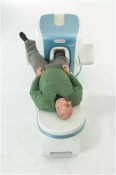
O-scan is manufactured and distributed by Esaote SpA
O-scan is a compact, dedicated extremity MRI system designed for easy installation and high throughput. The complete system fits in a 9' x 10' room, doesn't need for RF or magnetic shielding and it plugs in the wall. The 0.31T permanent magnet along with dual phased array RF coils, and advanced imaging protocols provide outstanding image quality and fast 25 minute complete examinations.
Esaote North America is the exclusive distributor of the O-scan system in the USA.
Device Information and Specification CLINICAL APPLICATION Dedicated Extremity
PULSE SEQUENCES
SE, HSE, HFE, GE, 2dGE, ME, IR, STIR, Stir T2, GESTIR, TSE, TME, FSE STIR, FSE ( T1, T2), X-Bone, Turbo 3DT1, 3D SHARC, 3D SST1, 3D SST2 2D: 2mm - 10 mm, 3D: 0.6 - 10 mm POWER REQUIREMENTS 100/110/200/220/230/240 | | | | | |
| | | Searchterm 'Image Quality' was also found in the following services: | | | | |
| | |
| |
|
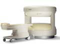
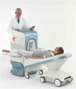
From Philips Medical Systems;
this active shielded member of the Panorama product line combines the advantages of one 1.0 T system's with the possibilities of an open MRI system. The open design helps ease anxiety for claustrophobic patients and increased patient comfort whereby the field strength provides spectacular image quality and fast patient throughput.
Device Information and Specification CLINICAL APPLICATION Whole body Vertically opposed solenoids, head, head-neck, extremity, neck, body/ spine M-XL, shoulder, bilateral breast, wrist, TMJ, flex XS-S-M-L-XL-XXL SE, FE, IR, STIR, FFE, DEFFE, DESE, TSE, DETSE, Single shot SE, DRIVE, Balanced FFE, MRCP, FLAIR, Turbo FLAIR, IR-TSE, T1-STIR TSE, T2-STIR TSE, Diffusion Imaging, 3D SE, 3D FFE, Contrast Perfusion Analysis, MTC;; Angiography: CE-ANGIO, MRA 2D, 3D TOFOpen x 47 cm x infinite (side-first patient entry) POWER REQUIREMENTS 400/480 V | | | |
• View the DATABASE results for 'Panorama 1.0T™' (2).
| | | | |
| | | | |
| | | |
|
| |
 | Look
Ups |
| |


