 | Info
Sheets |
| | | | | | | | | | | | | | | | | | | | | | | | |
 | Out-
side |
| | | | |
|
| | | | |
Result : Searchterm 'Gradient and Spin Echo' found in 1 term [ ] and 2 definitions [ ] and 2 definitions [ ], (+ 18 Boolean[ ], (+ 18 Boolean[ ] results ] results
| | previous 11 - 15 (of 21) nextResult Pages : [1] [2 3 4 5] |  | | | | |  |
| |
|
(GRE - sequence) A gradient echo is generated by using a pair of bipolar gradient pulses. In the pulse sequence timing diagram, the basic gradient echo sequence is illustrated. There is no refocusing 180° pulse and the data are sampled during a gradient echo, which is achieved by dephasing the spins with a negatively pulsed gradient before they are rephased by an opposite gradient with opposite polarity to generate the echo.
See also the Pulse Sequence Timing Diagram. There you will find a description of the components.
The excitation pulse is termed the alpha pulse α. It tilts the magnetization by a flip angle α, which is typically between 0° and 90°. With a small flip angle there is a reduction in the value of transverse magnetization that will affect subsequent RF pulses.
The flip angle can also be slowly increased during data acquisition (variable flip angle: tilt optimized nonsaturation excitation).
The data are not acquired in a steady state, where z-magnetization recovery and destruction by ad-pulses are balanced.
However, the z-magnetization is used up by tilting a little more of the remaining z-magnetization into the xy-plane for each acquired imaging line.
Gradient echo imaging is typically accomplished by examining the FID, whereas the read gradient is turned on for localization of the signal in the readout direction. T2* is the characteristic decay time constant associated with the FID. The contrast and signal generated by a gradient echo depend on the size of the longitudinal magnetization and the flip angle.
When α = 90° the sequence is identical to the so-called partial saturation or saturation recovery pulse sequence.
In st andard GRE imaging, this basic pulse sequence is repeated as many times as image lines have to be acquired.
Additional gradients or radio frequency pulses are introduced with the aim to spoil to refocus the xy-magnetization at the moment when the spin system is subject to the next α pulse.
As a result of the short repetition time, the z-magnetization cannot fully recover and after a few initial α pulses there is an equilibrium established between z-magnetization recovery and z-magnetization reduction due to the α pulses.
Gradient echoes have a lower SAR, are more sensitive to field inhomogeneities and have a reduced crosstalk, so that a small or no slice gap can be used.
In or out of phase imaging depending on the selected TE ( and field strength of the magnet) is possible.
As the flip angle is decreased, T1 weighting can be maintained by reducing the TR.
T2* weighting can be minimized by keeping the TE as short as possible, but pure T2 weighting is not possible.
By using a reduced flip angle, some of the magnetization value remains longitudinal (less time needed to achieve full recovery) and for a certain T1 and TR, there exist one flip angle that will give the most signal, known as the "Ernst angle".
Contrast values:
PD weighted: Small flip angle (no T1), long TR (no T1) and short TE (no T2*)
T1 weighted: Large flip angle (70°), short TR (less than 50ms) and short TE
T2* weighted: Small flip angle, some longer TR (100 ms) and long TE (20 ms)
Classification of GRE sequences can be made into four categories:
See also Gradient Recalled Echo Sequence, Spoiled Gradient Echo Sequence, Refocused Gradient Echo Sequence, Ultrafast Gradient Echo Sequence.
| | | | | | | | | | | | |  Further Reading: Further Reading: | | Basics:
|
|
News & More:
| |
| |
| | | | | |
| |
|
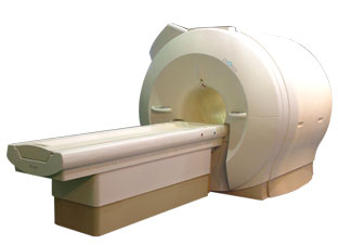
'Next generation MRI system 1.5T CHORUS developed by ISOL Technology is optimized for both clinical diagnostic imaging and for research development.
CHORUS offers the complete range of feature oriented advanced imaging techniques- for both clinical routine and research. The compact short bore magnet, the patient friendly design and the gradient technology make the innovation to new degree of perfection in magnetic resonance.'
Device Information and Specification
CLINICAL APPLICATION
Whole body
Spin Echo, Gradient Echo, Fast Spin Echo,
Inversion Recovery ( STIR, Fluid Attenuated Inversion Recovery), FLASH, FISP, PSIF, Turbo Flash ( MPRAGE ),TOF MR Angiography, St andard echo planar imaging package (SE-EPI, GE-EPI), Optional:
Advanced P.A. Imaging Package (up to 4 ch.), Advanced echo planar imaging package,
Single Shot and Diffusion Weighted EPI, IR/FLAIR EPI
STRENGTH
20 mT/m (Upto 27 mT/m)
| | | |
• View the DATABASE results for 'CHORUS 1.5T™' (2).
| | | | |
| | | | | |
| |
|
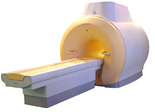
'MRI system is not an expensive equipment anymore.
ENCORE developed by ISOL Technology is a low cost MRI system with the advantages like of the 1.0T MRI scanner. Developed specially for the overseas market, the ENCORE is gaining popularity in the domestic market by medium sized hospitals.
Due to the optimum RF and Gradient application technology. ENCORE enables to obtain high resolution imaging and 2D/3D Angio images which was only possible in high field MR systems.'
- Less consumption of the helium gas due to the ultra-lightweight magnet specially designed and manufactured for ISOL.
- Cost efficiency MR system due to air cooling type (equivalent to permanent magnetic).
- Patient processing speed of less than 20 minutes.'
Device Information and Specification
CLINICAL APPLICATION
Whole body
CONFIGURATION
Short bore compact
| | | |
• View the DATABASE results for 'ENCORE 0.5T™' (2).
| | | | |
| | | | | |
| |
|
| | | | | | | |
• View the DATABASE results for 'Lung Imaging' (7).
| | |
• View the NEWS results for 'Lung Imaging' (3).
| | | | | | Further Reading: | | Basics:
|
|
News & More:
|  |
Chest MRI a viable alternative to chest CT in COVID-19 pneumonia follow-up
Monday, 21 September 2020 by www.healthimaging.com | | |
CT Imaging Features of 2019 Novel Corona virus (2019-nCoV)
Tuesday, 4 February 2020 by pubs.rsna.org | | |
Polarean Imaging Phase III Trial Results Point to Potential Improvements in Lung Imaging
Wednesday, 29 January 2020 by www.diagnosticimaging.com | | |
Low Power MRI Helps Image Lungs, Brings Costs Down
Thursday, 10 October 2019 by www.medgadget.com | | |
Chest MRI Using Multivane-XD, a Novel T2-Weighted Free Breathing MR Sequence
Thursday, 11 July 2019 by www.sciencedirect.co | | |
Researchers Review Importance of Non-Invasive Imaging in Diagnosis and Management of PAH
Wednesday, 11 March 2015 by lungdiseasenews.com | | |
New MRI Approach Reveals Bronchiectasis' Key Features Within the Lung
Thursday, 13 November 2014 by lungdiseasenews.com | | |
MRI techniques improve pulmonary embolism detection
Monday, 19 March 2012 by medicalxpress.com |
|
News & More:
| |
| |
| | | | | |
| |
|
Quick Overview Please note that there are different common names for this artifact.
DESCRIPTION
Black or bright band
During frequency encoding, fat protons precess slower than water protons in the same slice because of their magnetic shielding. Through the difference in resonance frequency between water and fat, protons at the same location are misregistrated (dislocated) by the Fourier transformation, when converting MRI signals from frequency to spatial domain. This chemical shift misregistration cause accentuation of any fat-water interfaces along the frequency axis and may be mistaken for pathology. Where fat and water are in the same location, this artifact can be seen as a bright or dark b and at the edge of the anatomy.
Protons in fat and water molecules are separated by a chemical shift of about 3.5 ppm. The actual shift in Hertz (Hz) depends on the magnetic field strength of the magnet being used. Higher field strength increases the misregistration, while in contrast a higher gradient strength has a positive effect. For a 0.3 T system operating at 12.8 MHz the shift will be 44.8 Hz compared with a 223.6 Hz shift for a 1.5 T system operating at 63.9 MHz.

Image Guidance
| | | |
• View the DATABASE results for 'Chemical Shift Artifact' (7).
| | | | | | Further Reading: | Basics:
|
|
News & More:
| |
| |
| | | | |
| | | |
|
| |
 | Look
Ups |
| |


