 | Info
Sheets |
| | | | | | | | | | | | | | | | | | | | | | | | |
 | Out-
side |
| | | | |
|
| | | | | |  | Searchterm 'Gradient Echo Sequence' was also found in the following services: | | | | |
|  |  |
| |
|
(EPI) Echo planar imaging is one of the early magnetic resonance imaging sequences (also known as Intascan), used in applications like diffusion, perfusion, and functional magnetic resonance imaging. Other sequences acquire one k-space line at each phase encoding step. When the echo planar imaging acquisition strategy is used, the complete image is formed from a single data sample (all k-space lines are measured in one repetition time) of a gradient echo or spin echo sequence (see single shot technique) with an acquisition time of about 20 to 100 ms.
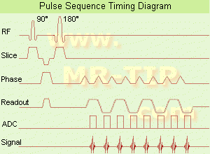
The pulse sequence timing diagram illustrates an echo planar imaging sequence from spin echo type with eight echo train pulses. (See also Pulse Sequence Timing Diagram, for a description of the components.)
In case of a gradient echo based EPI sequence the initial part is very similar to a standard gradient echo sequence. By periodically fast reversing the readout or frequency encoding gradient, a train of echoes is generated.
EPI requires higher performance from the MRI scanner like much larger gradient amplitudes. The scan time is dependent on the spatial resolution required, the strength of the applied gradient fields and the time the machine needs to ramp the gradients.
In EPI, there is water fat shift in the phase encoding direction due to phase accumulations. To minimize water fat shift (WFS) in the phase direction fat suppression and a wide bandwidth (BW) are selected. On a typical EPI sequence, there is virtually no time at all for the flat top of the gradient waveform. The problem is solved by "ramp sampling" through most of the rise and fall time to improve image resolution.
The benefits of the fast imaging time are not without cost. EPI is relatively demanding on the scanner hardware, in particular on gradient strengths, gradient switching times, and receiver bandwidth. In addition, EPI is extremely sensitive to image artifacts and distortions. | | | | | | | | | | |  Further Reading: Further Reading: | Basics:
|
|
| |
| | | | | |
| |
|
(EPI Factor) The imaging speed in Echo Planar Imaging (EPI) depends on many factors. Single shot EPI should provide images within 100 ms or less. Because of this limitations, a multi shot EPI approach is in most cases preferred. The parameter 'EPI Factor' is used to specify the number of k-space profiles collected per excitation. The EPI factor 64 means a measurement time 64 times faster than a normal gradient echo sequence.
See also Echo Planar Imaging. | | | |
• View the DATABASE results for 'Echo Planar Imaging Factor' (2).
| | | | | | Further Reading: | Basics:
|
|
| |
| | | | | |
| |
|
From ISOL Technology
'Ultra high field MR system, it's right close to you.
FORTE 3.0T is the new standard for the future ultra high field MR system.
If you are pushing the limits of your existing clinical MR scanner, the FORTE will surely take you to the next level of diagnostic imaging.
FORTE is the core leader of the medical technology in the 21st century. Proving effects of fMRI that cannot be measured with MRI less than 2.0T.'
Device Information and Specification
CLINICAL APPLICATION
Whole body
CONFIGURATION
Short bore compact
128 x 128, 256 x 256, 512 x 512, 1024 x 1024
| | | |
• View the DATABASE results for 'FORTE 3.0T™' (2).
| | | | |
| | | Searchterm 'Gradient Echo Sequence' was also found in the following services: | | | | |
| | |
| |
|
(FLASH) A fast sequence producing signals called gradient echo with low flip angles. FLASH sequences are modifications, which incorporate or remove the effects of transverse coherence respectively.
FLASH uses a semi-random spoiler gradient after each echo to spoil the steady state (to destroy any remaining transverse magnetization) by causing a spatially dependent phase shift. The transverse steady state is spoiled but the longitudinal steady state depends on the T1 values and the flip angle. Extremely short TR times are possible, as a result the sequence provides a mechanism for gaining extremely high T1 contrast by imaging with TR times as brief as 20 to 30 msec while retaining reasonable signal levels. It is important to keep the TE as short as possible to suppress susceptibility artifacts.
The T1 contrast depends on the TR as well as on flip angle, with short TE.
Small flip angles and short TR results in proton density, and long TR in T2* weighting.
With large flip angles and short TR result T1 weighted images.
TR and flip angle adjustment:
TR 3000 ms, Flip Angle 90°
TR 1500 ms, Flip Angle 45°
TR 700 ms, Flip Angle 25°
TR 125 ms, Flip Angle 10°
The apparent ability to trade TR against flip angle for purposes of contrast and the variation in SNR as the scan time (TR) is reduced.
See also Gradient Echo Sequence. | | | | | |
• View the DATABASE results for 'Fast Low Angle Shot' (5).
| | | | | | Further Reading: | News & More:
|
|
| |
| | | | | |
| |
|
| | | |
• View the DATABASE results for 'Field Echo' (22).
| | |
• View the NEWS results for 'Field Echo' (1).
| | | | |
| | | | |
| | |
| | | |
|
| |
 | Look
Ups |
| |


