 | Info
Sheets |
| | | | | | | | | | | | | | | | | | | | | | | | |
 | Out-
side |
| | | | |
|
| | | | |
Result : Searchterm 'Gradient Coils' found in 1 term [ ] and 15 definitions [ ] and 15 definitions [ ], (+ 18 Boolean[ ], (+ 18 Boolean[ ] results ] results
| | previous 11 - 15 (of 34) nextResult Pages : [1] [2 3 4] [5 6 7] |  | | | | | | | | |  |
| |
|
| | | | | | | | |
• View the DATABASE results for 'Hardware' (19).
| | |
• View the NEWS results for 'Hardware' (1).
| | | | |  Further Reading: Further Reading: | | Basics:
|
|
News & More:
| |
| |
| | | | | |
| |
|
| | | | | | | | |
• View the DATABASE results for 'MRI Equipment' (13).
| | |
• View the NEWS results for 'MRI Equipment' (4).
| | | | | | Further Reading: | News & More:
|
|
| |
| | | | |
| |
|
| | | | | |
• View the DATABASE results for 'Paired Saddle Coil' (2).
| | | | | | Further Reading: | Basics:
|
|
| |
| | | | | |
| |
|
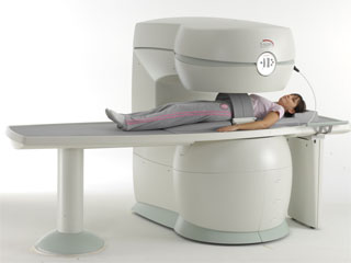
From Esaote S.p.A.;
Esaote introduced the S-SCAN at RSNA in November 2007. The S-SCAN is a dedicated joint and spine MR scanner derived from the company's earlier G-SCAN system. Unlike the G-SCAN, neither the patient table nor
the magnet can rotate from horizontal to vertical position. The patient table can only moved manually. Improved electronics, new coils for lumbar and cervical spine, new pulse sequences, a modified version of the magnet poles and gradient coils are used with a new software release in the S-SCAN.
Esaote North America is the exclusive U.S. distributor of this MRI device.
Device Information and Specification SE, GE, IR, STIR, TSE, 3D CE, GE-STIR, 3D GE, ME, TME, HSE POWER REQUIREMENTS 3 kW; 110/220 V single phase | | | |
• View the DATABASE results for 'S-SCAN' (3).
| | |
• View the NEWS results for 'S-SCAN' (1).
| | | | | | Further Reading: | News & More:
|
|
| |
| | | | |
| | | |
|
| |
 | Look
Ups |
| |


