| Info
Sheets |
| | | | | | | | | | | | | | | | | | | | | | | | |
 | Out-
side |
| | | | |
|
| | | | | |  | Searchterm 'Field Strength' was also found in the following services: | | | | |
|  |  |
| |
|
[B 1] A conventional symbol for the radio frequency field strength (another symbol historically used, is H1). In MRI, B1 labels the field produced by the radio frequency coil.
The B1 field is often conceived of two vectors rotating in opposite directions, usually in a plane transverse to B0. At the Larmor frequency, the vector rotating in the same direction as the precessing spins will interact strongly with the spins. | | | | | | | | | | |  Further Reading: Further Reading: | News & More:
|
|
| |
| | | Searchterm 'Field Strength' was also found in the following services: | | | | |
| | |
| |
|
(BW) Bandwidth is a measure of frequency range, the range between the highest and lowest frequency allowed in the signal. For analog signals, which can be mathematically viewed as a function of time, bandwidth is the width, measured in Hertz of a frequency range in which the signal's Fourier transform is nonzero.

Image Guidance
| | | |
• View the DATABASE results for 'Bandwidth' (19).
| | | | | | Further Reading: | | Basics:
|
|
News & More:
| |
| |
| | | | | |
| |
|
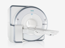
FDA cleared and CE Mark 2011.
The Biograph mMR has a fully-integrated design for simultaneous PET/MRI imaging. The dedicated hardware includes solid-state, avalanche photodiode PET detector and adapted, PET-compatible MR coils.
The possibility of truly simultaneous operation allows the acquisition of several magnetic resonance imaging ( MRI) sequences during the positron emission tomography (PET) scan, without increasing the examination time.
See also Hybrid Imaging.
Device Information and Specification
CLINICAL APPLICATION
Whole Body
CONFIGURATION
Simultaneous PET/MRI
26 cm (typical overlap 23%)
A-P 45, R-L 50, H-F 50 cm
PET RING DIAMETER
65.6 cm
PATIENT SCAN RANGE
199 cm
HORIZONTAL SPEED
200 mmsec
PET DETECTOR
Solid state, 4032 avalanche photo diodes
DETECTOR SCINTILLATION MATERIAL
LSO, 28672 crystals
CRYSTAL SIZE
4 x 4 x 20 mm
DIMENSION H*W*D (gantry included)
335 x 230 x 242 cm (finshed covers)
COOLING SYSTEM
PET system: water; MRI system: water
Aautomatic, patient specific shim; active shim 3 linear and 5 non-linear channels (seond order)
POWER REQUIREMENTS
380 / 400 / 420 / 440 / 460 / 480 V, 3-phase + ground; Total system 110kW
| | | | | | | Further Reading: | Basics:
|
|
News & More:
| |
| |
| | | Searchterm 'Field Strength' was also found in the following services: | | | | |
| | |
| |
|
(MR mammography) Magnetic resonance imaging of the breast is particularly useful in evaluation of newly diagnosed breast cancer, in women whose breast tissue is mammographically very dense and for screening in women with a high lifetime risk of breast cancer because of their family history or genetic disposition.
Breast MRI can be performed on all standard whole body magnets at a field strength of 0.5 T - 1.5 Tesla. Powerful gradient strengths over 15 mT/m will help to improve the balance between spatial resolution, scanning speed, and volume coverage. The use of a dedicated bilateral breast coil is obligatory.
Malignant lesions release angiogenic factors that increase local vessel density and vessel permeability. Breast cancer is detectable due to the strong enhancement in dynamic breast imaging that peaks early (about 1-2 min.) after contrast medium injection. If breast cancer is suspected, a breast biopsy may be necessary to secure the diagnosis. See also Magnetic Resonance Imaging MRI, Biopsy and MR Guided Interventions.
Requirements in breast MRI procedures:
•
Both breasts must be measured without gaps.
•
For the best possible detection of enhancement fat signal should be eliminated either by image subtraction or by
spectrally selective fat saturation.
•
Thin slices are necessary to assure absence of partial
volume effects.
•
Imaging should be performed with a spatial
resolution in plane less than 1 mm.
For Ultrasound Imaging (USI) see Breast Ultrasound at Medical-Ultrasound-Imaging.com.
See also the related poll result: ' MRI will have replaced 50% of x-ray exams by' | | | | | | | | | | |
• View the DATABASE results for 'Breast MRI' (13).
| | |
• View the NEWS results for 'Breast MRI' (41).
| | | | | | Further Reading: | Basics:
|
|
News & More:
|  |
Technology advances in breast cancer screenings lead to early diagnosis
Friday, 6 October 2023 by ksltv.com | | |
Are synthetic contrast-enhanced breast MRI images as good as the real thing?
Friday, 18 November 2022 by healthimaging.com | | |
Abbreviated breast MRI protocols not as cost-effective as promised, new study shows
Wednesday, 20 July 2022 by healthimaging.com | | |
Deep learning poised to improve breast cancer imaging
Thursday, 24 February 2022 by www.eurekalert.org | | |
Pre-Operative Breast MRI Can Help Identify Patients Likely to Experience Nipple-Sparing Mastectomy Risks
Wednesday, 7 April 2021 by www.diagnosticimaging.com | | |
Breast cancer screening recalls: simple MRI measurement could avoid 30% of biopsies
Monday, 1 March 2021 by www.eurekalert.org | | |
A Comparison of Methods for High-Spatial-Resolution Diffusion-weighted Imaging in Breast MRI
Tuesday, 25 August 2020 by pubs.rsna.org | | |
Pre-Operative Breast MRI Diagnoses More Cancers in Women with DCIS
Thursday, 9 July 2020 by www.diagnosticimaging.com | | |
Breast MRI and tumour biology predict axillary lymph node response to neoadjuvant chemotherapy for breast cancer
Thursday, 26 December 2019 by cancerimagingjournal.biomedcentral.com | | |
Breast MRI Coding Gets an Overhaul in 2019
Wednesday, 9 January 2019 by www.aapc.com | | |
How accurate are volumetric software programs when compared to breast MRI?
Thursday, 27 July 2017 by www.radiologybusiness.com | | |
Additional Breast Cancer Tumors Found on MRI After Mammography May Be Larger, More Aggressive
Wednesday, 9 December 2015 by www.oncologynurseadvisor.com | | |
Preoperative MRI May Overdiagnose Contralateral Breast Cancer
Wednesday, 2 December 2015 by www.cancertherapyadvisor.com | | |
BI-RADS and breast MRI useful in predicting malignancy
Wednesday, 30 May 2012 by www.oncologynurseadvisor.com |
|
| |
| | | Searchterm 'Field Strength' was also found in the following services: | | | | |
| | |
| |
|
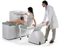
Device Information and Specification
CLINICAL APPLICATION
Dedicated extremity
SE, GE, IR, STIR, FSE, 3D CE, GE-STIR, 3D GE, ME, TME, HSE
IMAGING MODES
Single, multislice, volume study, fast scan, multi slab
2D: 2 mm - 10 mm;
3D: 0.6 mm - 10 mm
4,096 gray lvls, 256 lvls in 3D
POWER REQUIREMENTS
100/110/200/220/230/240
| | | |
• View the DATABASE results for 'C-SCAN™' (4).
| | | | |
| | | | |
| | | |
|
| |
 | Look
Ups |
| |