 | Info
Sheets |
| | | | | | | | | | | | | | | | | | | | | | | | |
 | Out-
side |
| | | | |
|
| | | | |
Result : Searchterm 'T1 Time' found in 1 term [ ] and 14 definitions [ ] and 14 definitions [ ], (+ 19 Boolean[ ], (+ 19 Boolean[ ] results ] results
| | previous 16 - 20 (of 34) nextResult Pages : [1] [2 3] [4 5 6 7] |  | |  | Searchterm 'T1 Time' was also found in the following services: | | | | |
| |  |
| |
|
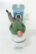
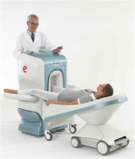
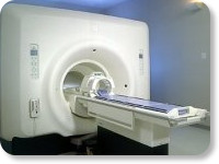
O-scan is manufactured and distributed by Esaote SpA
O-scan is a compact, dedicated extremity MRI system designed for easy installation and high throughput. The complete system fits in a 9' x 10' room, doesn't need for RF or magnetic shielding and it plugs in the wall. The 0.31T permanent magnet along with dual phased array RF coils, and advanced imaging protocols provide outstanding image quality and fast 25 minute complete examinations.
Esaote North America is the exclusive distributor of the O-scan system in the USA.
Device Information and Specification CLINICAL APPLICATION Dedicated Extremity
PULSE SEQUENCES
SE, HSE, HFE, GE, 2dGE, ME, IR, STIR, Stir T2, GESTIR, TSE, TME, FSE STIR, FSE ( T1, T2), X-Bone, Turbo 3D T1, 3D SHARC, 3D SS T1, 3D SST2 2D: 2mm - 10 mm, 3D: 0.6 - 10 mm POWER REQUIREMENTS 100/110/200/220/230/240 | | | | | |
| | | | | |
| |
|
(SE) The most common pulse sequence used in MR imaging is based of the detection of a spin or Hahn echo. It uses 90° radio frequency pulses to excite the magnetization and one or more 180° pulses to refocus the spins to generate signal echoes named spin echoes (SE).
In the pulse sequence timing diagram, the simplest form of a spin echo sequence is illustrated.
The 90° excitation pulse rotates the longitudinal magnetization ( Mz) into the xy-plane and the dephasing of the transverse magnetization (Mxy) starts.
The following application of a 180° refocusing pulse (rotates the magnetization in the x-plane) generates signal echoes. The purpose of the 180° pulse is to rephase the spins, causing them to regain coherence and thereby to recover transverse magnetization, producing a spin echo.
The recovery of the z-magnetization occurs with the T1 relaxation time and typically at a much slower rate than the T2-decay, because in general T1 is greater than T2 for living tissues and is in the range of 100-2000 ms.
The SE pulse sequence was devised in the early days of NMR days by Carr and Purcell and exists now in many forms: the multi echo pulse sequence using single or multislice acquisition, the fast spin echo (FSE/TSE) pulse sequence, echo planar imaging (EPI) pulse sequence and the gradient and spin echo (GRASE) pulse sequence;; all are basically spin echo sequences.
In the simplest form of SE imaging, the pulse sequence has to be repeated as many times as the image has lines. Contrast values:
PD weighted: Short TE (20 ms) and long TR.
T1 weighted: Short TE (10-20 ms) and short TR (300-600 ms)
T2 weighted: Long TE (greater than 60 ms) and long TR (greater than 1600 ms)
With spin echo imaging no T2* occurs, caused by the 180° refocusing pulse. For this reason, spin echo sequences are more robust against e.g., susceptibility artifacts than gradient echo sequences.
See also Pulse Sequence Timing Diagram to find a description of the components.
| | | | | |
• View the DATABASE results for 'Spin Echo Sequence' (24).
| | | | |  Further Reading: Further Reading: | | Basics:
|
|
News & More:
| |
| |
| | | | | |
| |
|
•
In the 1930's, Isidor Isaac Rabi (Columbia University) succeeded in detecting and measuring single states of rotation of atoms and molecules, and in determining the mechanical and magnetic moments of the nuclei.
•
Felix Bloch (Stanford University) and Edward Purcell (Harvard University) developed instruments, which could measure the magnetic resonance in bulk material such as liquids and solids. (Both honored with the Nobel Prize for Physics in 1952.) [The birth of the NMR spectroscopy]
•
In the early 70's, Raymond Damadian (State University of New York) demonstrated with his NMR device, that there are different T1 relaxation times between normal and abnormal tissues of the same type, as well as between different types of normal tissues.
•
In 1973, Paul Lauterbur (State University of New York) described a new imaging technique that he termed Zeugmatography. By utilizing gradients in the magnetic field, this technique was able to produce a two-dimensional image (back-projection). (Through analysis of the characteristics of the emitted radio waves, their origin could be determined.) Peter Mansfield further developed the utilization of gradients in the magnetic field and the mathematically analysis of these signals for a more useful imaging technique. (Paul C Lauterbur and Peter Mansfield were awarded with the 2003 Nobel Prize in Medicine.)
•
1977/78: First images could be presented.
A cross section through a finger by Peter Mansfield and Andrew A. Maudsley.
Peter Mansfield also could present the first image through the abdomen.
•
In 1977, Raymond Damadian completed (after 7 years) the first MR scanner (Indomitable). In 1978, he founded the FONAR Corporation, which manufactured the first commercial MRI scanner in 1980. Fonar went public in 1981.
•
1981: Schering submitted a patent application for Gd-DTPA dimeglumine.
•
1982: The first 'magnetization-transfer' imaging by Robert N. Muller.
•
In 1983, Toshiba obtained approval from the Ministry of Health and Welfare in Japan for the first commercial MRI system.
•
1986: Jürgen Hennig, A. Nauerth, and Hartmut Friedburg (University of Freiburg) introduced RARE (rapid acquisition with relaxation enhancement) imaging. Axel Haase, Jens Frahm, Dieter Matthaei, Wolfgang Haenicke, and Dietmar K. Merboldt (Max-Planck-Institute, Göttingen) developed the FLASH ( fast low angle shot) sequence.
•
1988: Schering's MAGNEVIST gets its first approval by the FDA.
•
In 1991, fMRI was developed independently by the University of Minnesota's Center for Magnetic Resonance Research (CMRR) and Massachusetts General Hospital's (MGH) MR Center.
•
From 1992 to 1997 Fonar was paid for the infringement of it's patents from 'nearly every one of its competitors in the MRI industry including giant multi-nationals as Toshiba, Siemens, Shimadzu, Philips and GE'.
| | | | | |
• View the DATABASE results for 'MRI History' (6).
| | |
• View the NEWS results for 'MRI History' (1).
| | | | | | Further Reading: | | Basics:
|
|
News & More:
| |
| |
| | | Searchterm 'T1 Time' was also found in the following services: | | | | |
| | |
| |
|
(FSE) In the pulse sequence timing diagram, a fast spin echo sequence with an echo train length of 3 is illustrated.
This sequence is characterized by a series of rapidly applied 180° rephasing pulses and multiple echoes, changing the phase encoding gradient for each echo.
The echo time TE may vary from echo to echo in the echo train. The echoes in the center of the K-space (in the case of linear k-space acquisition) mainly produce the type of image contrast, whereas the periphery of K-space determines the spatial resolution. For example, in the middle of K-space the late echoes of T2 weighted images are encoded. T1 or PD contrast is produced from the early echoes.
The benefit of this technique is that the scan duration with, e.g. a turbo spin echo turbo factor / echo train length of 9, is one ninth of the time. In T1 weighted and proton density weighted sequences, there is a limit to how large the ETL can be (e.g. a usual ETL for T1 weighted images is between 3 and 7). The use of large echo train lengths with short TE results in blurring and loss of contrast. For this reason, T2 weighted imaging profits most from this technique.
In T2 weighted FSE images, both water and fat are hyperintense. This is because the succession of 180° RF pulses reduces the spin spin interactions in fat and increases its T2 decay time. Fast spin echo (FSE) sequences have replaced conventional T2 weighted spin echo sequences for most clinical applications. Fast spin echo allows reduced acquisition times and enables T2 weighted breath hold imaging, e.g. for applications in the upper abdomen.
In case of the acquisition of 2 echoes this type of a sequence is named double fast spin echo / dual echo sequence, the first echo is usually density and the second echo is T2 weighted image. Fast spin echo images are more T2 weighted, which makes it difficult to obtain true proton density weighted images. For dual echo imaging with density weighting, the TR should be kept between 2000 - 2400 msec with a short ETL (e.g., 4).
Other terms for this technique are:
Turbo Spin Echo
Rapid Imaging Spin Echo,
Rapid Spin Echo,
Rapid Acquisition Spin Echo,
Rapid Acquisition with Refocused Echoes
| | | | | |
• View the DATABASE results for 'Fast Spin Echo' (31).
| | | | | | Further Reading: | Basics:
|
|
News & More:
| |
| |
| | | | | |
| |
|
(Signa VH/i 3.0T)
With GE Healthcare
leading-edge technology in ultra-high-field imaging. The 3 T VH/i provides a platform for advanced applications in radiology, cardiology, psychology and psychiatry. Real- time image processing lets you acquire multislice whole brain images and map brain functions for research or surgical planning. And the 3 T Signa VH/i is flexible enough to provide clinicians with high performance they require. It can provide not only outstanding features in brain scanning and neuro-system research, but also a wide range of use in scanning breasts, extremities, the spine and the cardiovascular systems.
Device Information and Specification CLINICAL APPLICATION Whole body
T/R quadrature head, T/R quadrature body, T/R phased array extremity (opt) SE, IR, 2D/3D GRE, FGRE, RF-spoiled GRE, FSE, Angiography: 2D/3D TOF, 2D/3D phase contrast vascular IMAGING MODES Single, multislice, volume study, fast scan, multi slab, cine, localizer 100 Images/sec with Reflex100 MULTISLICE 100 Images/sec with Reflex100 2D 0.5-100mm in 0.1mm incremental 128x512 steps 32 phase encode H*W*D 260cm x 238cm x 265cm POWER REQUIREMENTS 480 or 380/415, 3 phase ||
COOLING SYSTEM TYPE Closed-loop water-cooled grad. Less than 0.14 L/hr liquid He | | | |
• View the DATABASE results for 'Signa 3.0T™' (2).
| | | | |
| | | | |
| | | |
|
| |
 | Look
Ups |
| |


