| Info
Sheets |
| | | | | | | | | | | | | | | | | | | | | | | | |
 | Out-
side |
| | | | |
|
| | | | | |  | Searchterm 'Resolution' was also found in the following services: | | | | |
|  |  |
| |
|
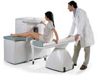
Device Information and Specification
CLINICAL APPLICATION
Dedicated extremity
SE, GE, IR, STIR, FSE, 3D CE, GE-STIR, 3D GE, ME, TME, HSE
IMAGING MODES
Single, multislice, volume study, fast scan, multi slab
2D: 2 mm - 10 mm;
3D: 0.6 mm - 10 mm
4,096 gray lvls, 256 lvls in 3D
POWER REQUIREMENTS
100/110/200/220/230/240
| | | | | |
| | | Searchterm 'Resolution' was also found in the following services: | | | | |
| | |
| |
|
(CSI) Chemical shift imaging is an extension of MR spectroscopy, allowing metabolite information to be measured in an extended region and to add the chemical analysis of body tissues to the potential clinical utility of Magnetic Resonance. The spatial location is phase encoded and a spectrum is recorded at each phase encoding step to allow the spectra acquisition in a number of volumes covering the whole sample. CSI provides mapping of chemical shifts, analog to individual spectral lines or groups of lines.
Spatial resolution can be in one, two or three dimensions, but with long acquisition times od full 3D CSI. Commonly a slice-selected 2D acquisition is used. The chemical composition of each voxel is represented by spectra, or as an image in which the signal intensity depends on the concentration of an individual metabolite. Alternatively frequency-selective pulses excite only a single spectral component.
There are several methods of performing chemical shift imaging, e.g. the inversion recovery method, chemical shift selective imaging sequence, chemical shift insensitive slice selective RF pulse, the saturation method, spatial and chemical shift encoded excitation and quantitative chemical shift imaging.
See also Magnetic Resonance Spectroscopy. | | | |
• View the DATABASE results for 'Chemical Shift Imaging' (6).
| | | | |  Further Reading: Further Reading: | | Basics:
|
|
News & More:
| |
| |
| | | | | |
| |
|
Cine sequences used in cardiovascular MRI are collection of images (usually at the same spatial location) covering of one full period of cardiac cycle or over several periods in order to obtain complete coverage.
The pulse sequence used, is either a standard gradient echo pulse sequence, a segmented data acquisition, a gradient echo EPI sequence or a gradient echo with balanced gradient waveform.
In cardiac gating studies it is possible to assign consecutive lines either to different images, yielding a multiphase sequence with as many images as lines, or the lines are grouped together into segments and assigned to the same image. The overall time to acquire such a segment has to be small compared to the RR-interval of the cardiac cycle, i. e. 50 ms, and hence contains typically 8 to 16 image lines.
This strategy is called segmented data acquisition, and has the advantage of reducing overall imaging time for cardiac images so that they can be acquired within a breath hold, but obviously decreasing the temporal resolution of each individual image.
This method shows dynamic processes, such as the ejection of blood out of the heart into the aorta, by means of fast imaging and displaying the resulting images in a sequential-loop, the impression of a real-time movie is generated. Ejection fractions and stroke volumes calculated from these cine MRI images in different cardiac axes have been shown to be more accurate than any other imaging modality. See also Cardiac Gating. | | | | | |
• View the DATABASE results for 'Cine Sequence' (2).
| | | | | | Further Reading: | News & More:
|
|
| |
| | | Searchterm 'Resolution' was also found in the following services: | | | | |
| | |
| |
|
| | | |
• View the DATABASE results for 'Coil Diameter' (3).
| | | | |
| | | Searchterm 'Resolution' was also found in the following services: | | | | |
| | |
| |
|
Contrast is the relative difference of signal intensities in two adjacent regions of an image.
Due to the T1 and T2 relaxation properties in magnetic resonance imaging, differentiation between various tissues in the body is possible. Tissue contrast is affected by not only the T1 and T2 values of specific tissues, but also the differences in the magnetic field strength, temperature changes, and many other factors. Good tissue contrast relies on optimal selection of appropriate pulse sequences ( spin echo, inversion recovery, gradient echo, turbo sequences and slice profile).
Important pulse sequence parameters are TR ( repetition time), TE (time to echo or echo time), TI (time for inversion or inversion time) and flip angle. They are associated with such parameters as proton density and T1 or T2 relaxation times. The values of these parameters are influenced differently by different tissues and by healthy and diseased sections of the same tissue.
For the T1 weighting it is important to select a correct TR or TI. T2 weighted images depend on a correct choice of the TE. Tissues vary in their T1 and T2 times, which are manipulated in MRI by selection of TR, TI, and TE, respectively. Flip angles mainly affect the strength of the signal measured, but also affect the TR/TI/TE parameters.
Conditions necessary to produce different weighted images:
T1 Weighted Image: TR value equal or less than the tissue specific T1 time - TE value less than the tissue specific T2 time.
T2 Weighted Image: TR value much greater than the tissue specific T1 time - TE value greater or equal than the tissue specific T2 time.
Proton Density Weighted Image: TR value much greater than the tissue specific T1 time - TE value less than the tissue specific T2 time.
See also Image Contrast Characteristics, Contrast Reversal, Contrast Resolution, and Contrast to Noise Ratio. | | | | | |
• View the DATABASE results for 'Contrast' (373).
| | |
• View the NEWS results for 'Contrast' (77).
| | | | | | Further Reading: | | Basics:
|
|
News & More:
| |
| |
| | | | |
| | | |
|
| |
 | Look
Ups |
| |