 | Info
Sheets |
| | | | | | | | | | | | | | | | | | | | | | | | |
 | Out-
side |
| | | | |
|
| | | | |
Result : Searchterm 'Quality Factor' found in 1 term [ ] and 1 definition [ ] and 1 definition [ ], (+ 9 Boolean[ ], (+ 9 Boolean[ ] results ] results
| | 1 - 5 (of 11) nextResult Pages : [1] [2 3] |  | | | | |  |
| |
|
The quality factor (Q) applies to any resonant circuit component; most often the quality factor of the coil determines the overall Q of the circuit.
Inversely related to the fraction of the energy in an oscillating system lost in one oscillation cycle. Q is inversely related to the range of frequency over which the system will exhibit resonance.
In a parallel tuned circuit (such as used in a MR coil), the quality factor is defined as:
Q = vL/R
where L is the coil inductance, R is the circuit resistance, and v is the angular frequency.
Increasing quality factor results in improving the signal to noise ratio SNR by a factor √Q and also produces a sharper frequency response (decreased band width). The Q of a coil will depend on the circumstances under which it is measured, e.g. whether it is 'unloaded' (no patient) or 'loaded' (patient). | | | | | | • Share the entry 'Quality Factor':    | | | | | | | | | |
| |  | Searchterm 'Quality Factor' was also found in the following service: | | | | |
| |  |
| |
|
| | | |
• View the DATABASE results for 'Coil Loading' (2).
| | | | |
| | | | |  |
| |
|
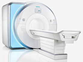
From Siemens Medical Systems;
Received FDA clearance in 2010.
MAGNETOM Skyra is a top-of-the-line, patient friendly wide bore 3 Tesla MRI system.
The system is equipped with the Tim 4G and Dot system (Total imaging matrix and Day optimizing throughput), to enhance both productivity and image quality with the complete range of advanced applications for clinical routine and research. Tim 4G features lighter, trimmer MRI coils that take up less space inside the magnet but deliver a high coil element density with increased signal to noise ratio and the possibility to use high iPAT factors.
Device Information and Specification
CLINICAL APPLICATION
Whole Body
Head, spine, torso/ body coil, neurovascular, cardiac, neck, shoulder, knee, wrist, foot//ankle and multi-purpose flex coils. Peripheral vascular, breast, shoulder.
CHANNELS (min. / max. configuration)
48, 64, 128
Chemical shift imaging, single voxel spectroscopy
MINIMUM TE
3D T1 spoiled GRE: 0.22 (256 matrix), Ultra-short TE
At isocenter: L-R 70 cm, A-P (with table) 55 cm
MAGNET WEIGHT (gantry included)
5768 kg
DIMENSION H*W*D (gantry included)
173 x 231 x 219 cm
COOLING SYSTEM
Water; single cryogen, 2 stage refrigeration
3 linear with 20 coils, 5 nonlinear 2nd-order
POWER REQUIREMENTS
380 / 400 / 420 / 440 / 460 / 480 V, 3-phase + ground; 110 kVA
| | | | | |
| | | | | |
| |
|
An image artifact is a structure not normally present but visible as a result of a limitation or malfunction in the hardware or software of the MRI device, or in other cases a consequence of environmental influences as heat or humidity or it can be caused by the human body (blood flow, implants etc.). The knowledge of MRI artifacts (brit. artefacts) and noise producing factors is important for continuing maintenance of high image quality. Artifacts may be very noticeable or just a few pixels out of balance but can give confusing artifactual appearances with pathology that may be misdiagnosed.
Changes in patient position, different pulse sequences, metallic artifacts, or other imaging variables can cause image distortions, which can be reduced by the operator; artifacts due to the MR system may require a service engineer.
Many types of artifacts may occur in magnetic resonance imaging. Artifacts in magnetic resonance imaging are typically classified as to their basic principles, e.g.:
•
Physiologic (motion, flow)
•
Hardware (electromagnetic spikes, ringing)
Several techniques are developed to reduce these artifacts (e.g. respiratory compensation, cardiac gating, eddy current compensation) but sometimes these effects can also be exploited, e.g. for flow measurements.
See also the related poll result: ' Most outages of your scanning system are caused by failure of'
| | | |
• View the DATABASE results for 'Artifact' (166).
| | | | |  Further Reading: Further Reading: | | Basics:
|
|
News & More:
| |
| |
| | | Searchterm 'Quality Factor' was also found in the following service: | | | | |
| | |
| |
|
(FOV) Defined as the size of the two or three dimensional spatial encoding area of the image. Usually defined in units of mm². The FOV is the square image area that contains the object of interest to be measured. The smaller the FOV, the higher the resolution and the smaller the voxel size but the lower the measured signal.
Useful for decreasing the scantime is a field of view different in the frequency and phase encoding directions ( rectangular field of view - RFOV).
The magnetic field homogeneity decreases as more tissue is imaged (greater FOV). As a result the precessional frequencies change across the imaging volume. That can be a problem for fat suppression imaging. This fat is precessing at the expected frequency only in the center of the imaging volume. E.g. frequency specific fat saturation pulses become less effective when the field of view is increased. It is best to use smaller field of views when applying fat saturation pulses.

Image Guidance
Smaller FOV required higher gradient strength and concludes low signal. Therefore you have to find a compromise between these factors.
The right choice of the field of view is important for MR image quality. When utilizing small field of views and scanning at a distance from the isocenter (more problems with artifacts) it is obviously important to ensure that the region of interest is within the scanning volume.
A smaller FOV in one direction is available with the function rectangular field of view (RFOV).
See also Field Inhomogeneity Artifact. | | | | | |
• View the DATABASE results for 'Field of View' (27).
| | | | | | Further Reading: | Basics:
|
|
News & More:
| |
| |
| | | | |
| | | 1 - 5 (of 11) nextResult Pages : [1] [2 3] |
| |
|
| |
 | Look
Ups |
| |


