Magnetic Resonance - Technology Information Portal Welcome to MRI Technology
Info
  Sheets

Out-
      side


 'Matrix' 
SEARCH FOR    
 
  2 3 5 A B C D E F G H I J K L M N O P Q R S T U V W X Y Z
Result : Searchterm 'Matrix' found in 6 terms [] and 79 definitions []
previous     61 - 65 (of 85)     next
Result Pages : [1 2]  [3 4 5 6 7 8 9 10 11 12 13 14 15 16 17]
Searchterm 'Matrix' was also found in the following services: 
spacer
News  (2)  Resources  (3)  Forum  (10)  
 
Annotation
 
A description of the factors used in creating an image should include the type and times of the pulse sequence, the number of signals averaged or added (NSA), the size of the reconstructed region, the size of the acquisition matrix in each direction, field of view and the slice thickness; usually printed at the border of MRI pictures.
spacer
Searchterm 'Matrix' was also found in the following services: 
spacer
Radiology  (12) Open this link in a new windowUltrasound  (6) Open this link in a new window
Aurora® 1.5T Dedicated Breast MRI SystemInfoSheet: - Devices -
Intro, 
Types of Magnets, 
Overview, 
etc.
 
www.auroramri.com/mri/product/ 
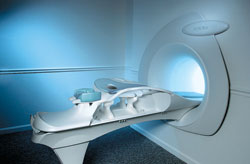
From Aurora Imaging Technology, Inc.;
The Aurora® 1.5T Dedicated Breast MRI System with Bilateral SpiralRODEO™ is the first and only FDA approved MRI device designed specifically for breast imaging. The Aurora System, which is already in clinical use at a growing number of leading breast care centers in the US, Europe, got in December 2006 also the approval from the State Food and Drug Administration of the People's Republic of China (SFDA).
'Some of the proprietary and distinguishing features of the Aurora System include: 1) an ellipsoid magnetic shim that provides coverage of both breasts, the chest wall and bilateral axillary lymph nodes; 2) a precision gradient coil with the high linearity required for high resolution spiral reconstruction;; 3) a patient-handling table that provides patient comfort and procedural utility; 4) a fully integrated Interventional System for MRI guided biopsy and localization; and 5) the user-friendly AuroraCAD™ computer-aided image display system designed to improve the accuracy and efficiency of diagnostic interpretations.'
Device Information and Specification
CLINICAL APPLICATION
CONFIGURATION
Short bore compact
IMAGING MODES
Bi-lateral RODEO fat suppression, high resolution Rotating Delivery of Excitation Offresonance Spiral, integrated targeting SW compatible with major MR guided intervention equipment
TR
10 ms for gradient echo and less than 2,500 ms for T2 weighted spin echo
TE
From 5 ms for RODEO Plus to over 80 ms, 120 ms for T2 sequences
SINGLE/MULTI SLICE
Around 0.02 sec for a 256x256 image, 12.4 sec for a 512 x 512 x 32 multislice set
FOV
20 - 36 cm, max. elliptical 36 x 44 cm
MEASURING MATRIX
512 x 512
BORE DIAMETER
or W x H
64 cm diameter (gantry)
MAGNET WEIGHT
8,500 lbs
H*W*D
240 x 188 x 163 cm
POWER REQUIREMENTS
150A/120V-208Y/3 Phase//60 Hz/5 Wire
COOLING SYSTEM
Helium for magnet, distilled/de-ionized water for coil;
spacer

• View the DATABASE results for 'Aurora® 1.5T Dedicated Breast MRI System' (2).Open this link in a new window


• View the NEWS results for 'Aurora® 1.5T Dedicated Breast MRI System' (3).Open this link in a new window.
 
Further Reading:
  News & More:
Aurora Imaging Technology Announces Approval in China
   by salesandmarketingnetwork.com    
Aurora Imaging Technology, Inc. Release: Results of a Multi-Center Trial Demonstrates Superior Diagnostic Performance of the Aurora® 1.5T Dedicated Breast MRI System Over Whole-Body Breast MRI
Monday, 1 October 2012   by www.biospace.com    
MRI Resources 
IR - Societies - Intraoperative MRI - - MRA - Collections
 
Black Boundary ArtifactInfoSheet: - Artifacts - 
Case Studies, 
Reduction Index, 
etc.MRI Resource Directory:
 - Artifacts -
 
Quick Overview
Please note that there are different common names for this artifact.
Artifact Information
NAME
Black boundary, dark boundary, contour, chemical shift, relief
DESCRIPTION
Black contours at boundaries
Black boundary artifacts are black lines following voxels where both water and fat protons are present in the same voxel. This artifact arise along the boundary of organs or tissues perpendicular to the frequency encoding direction, and occurs preferentially in gradient echo sequences with out of phase echo times.
mri safety guidance
Image Guidance
Fat suppression techniques eliminate this artifact. For artifact reducing helps a smaller water fat shift (high bandwidth), a higher matrix or/and an in phase TE.

See also Chemical Shift Artifact.
spacer

• View the DATABASE results for 'Black Boundary Artifact' (4).Open this link in a new window

 
Further Reading:
  Basics:
What is chemical shift artefact? Why does it occur? How many Hz at 1.5 T?
   by www.revisemri.com    
Searchterm 'Matrix' was also found in the following services: 
spacer
News  (2)  Resources  (3)  Forum  (10)  
 
Chemical Shift ArtifactInfoSheet: - Artifacts - 
Case Studies, 
Reduction Index, 
etc.MRI Resource Directory:
 - Artifacts -
 
Quick Overview
Please note that there are different common names for this artifact.
Artifact Information
NAME
Chemical shift, black boundary, spatial misregistration, relief
DESCRIPTION
Black or bright band
During frequency encoding, fat protons precess slower than water protons in the same slice because of their magnetic shielding. Through the difference in resonance frequency between water and fat, protons at the same location are misregistrated (dislocated) by the Fourier transformation, when converting MRI signals from frequency to spatial domain. This chemical shift misregistration cause accentuation of any fat-water interfaces along the frequency axis and may be mistaken for pathology. Where fat and water are in the same location, this artifact can be seen as a bright or dark band at the edge of the anatomy.
Protons in fat and water molecules are separated by a chemical shift of about 3.5 ppm. The actual shift in Hertz (Hz) depends on the magnetic field strength of the magnet being used. Higher field strength increases the misregistration, while in contrast a higher gradient strength has a positive effect. For a 0.3 T system operating at 12.8 MHz the shift will be 44.8 Hz compared with a 223.6 Hz shift for a 1.5 T system operating at 63.9 MHz.
mri safety guidance
Image Guidance
For artifact reduction helps a smaller water fat shift (higher bandwidth), a higher matrix, an in phase TE or a spin echo technique. Since the misregistration offset is present in the read out axis the patient may be rescanned with this axis parallel to the fat-water interface. Steeper gradient may be employed to reduce the chemical shift offset in mm. Another strategy is to employ specialized pulse sequences such as fat saturation or inversion recovery imaging. Fat suppression techniques eliminate chemical shift artifacts caused by the lack of fat signal.

See also Black Boundary Artifact and Magnetic Resonance Spectroscopy.
spacer

• View the DATABASE results for 'Chemical Shift Artifact' (7).Open this link in a new window

 
Further Reading:
  Basics:
MRI Artifact Gallery
   by chickscope.beckman.uiuc.edu    
  News & More:
What is chemical shift artefact? Why does it occur? How many Hz at 1.5 T?
   by www.revisemri.com    
Abdominal MRI at 3.0 T: The Basics Revisited
Wednesday, 20 July 2005   by www.ajronline.org    
Searchterm 'Matrix' was also found in the following services: 
spacer
Radiology  (12) Open this link in a new windowUltrasound  (6) Open this link in a new window
FORTE 3.0T™InfoSheet: - Devices -
Intro, 
Types of Magnets, 
Overview, 
etc.MRI Resource Directory:
 - Devices -
 
www.isoltech.co.kr/english/product/30t.htm 
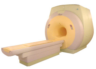
From ISOL Technology
'Ultra high field MR system, it's right close to you. FORTE 3.0T is the new standard for the future ultra high field MR system. If you are pushing the limits of your existing clinical MR scanner, the FORTE will surely take you to the next level of diagnostic imaging. FORTE is the core leader of the medical technology in the 21st century. Proving effects of fMRI that cannot be measured with MRI less than 2.0T.'
Device Information and Specification
CLINICAL APPLICATION
Whole body
CONFIGURATION
Short bore compact
SYNCHRONIZATION
ECG/peripheral: Optional/yes, external trigger, respiratory gating
PULSE SEQUENCES
Spin echo, Gradient echo, Fast spin echo, Inversion recovery, 2D/3D Fast gradient echo sequences FLAIR/STIR, 2D/3D TOF
IMAGING MODES
2D/3D, T1, T2 and Diffusion//Perfusion imaging, MR Angiography package, Advanced EPI package, Multi-nuclei MR Spectroscopy package
FOV
40 cm
128 x 128, 256 x 256, 512 x 512, 1024 x 1024
BORE DIAMETER
or W x H
61 cm without body coil
MAGNET WEIGHT
12000 kg
H*W*D
260 x 220 x 235 cm
COOLING SYSTEM TYPE
Water-cooled coil and air-cooled amplifier
CRYOGEN USE
0.15 L/hr helium
STRENGTH
38 mT/m
5-GAUSS FRINGE FIELD
3.3 m / 5.2 m
Passive and active
spacer

• View the DATABASE results for 'FORTE 3.0T™' (2).Open this link in a new window

MRI Resources 
Spectroscopy pool - General - Universities - Crystallography - Bioinformatics - Stent
 
previous      61 - 65 (of 85)     next
Result Pages : [1 2]  [3 4 5 6 7 8 9 10 11 12 13 14 15 16 17]
 Random Page
 
Share This Page
FacebookTwitterLinkedIn

MR-TIP    
Community   
User
Pass
Forgot your UserID/Password ?    


Next big thing in MRI will be :
AI 
remote operator 
personalized protocols 
helium-free 
molecular MRI 
portable MRI 

Look
      Ups


MR-TIP.com uses cookies! By browsing MR-TIP.com, you agree to our use of cookies.

Magnetic Resonance - Technology Information Portal
Member of SoftWays' Medical Imaging Group - MR-TIP • Radiology-TIP • Medical-Ultrasound-Imaging • 
Copyright © 2003 - 2024 SoftWays. All rights reserved. [ 19 April 2024]
Terms of Use | Privacy Policy | Advertising
 [last update: 2024-02-26 03:41:00]