 | Info
Sheets |
| | | | | | | | | | | | | | | | | | | | | | | | |
 | Out-
side |
| | | | |
|
| | | | |
Result : Searchterm 'Image Quality' found in 1 term [ ] and 44 definitions [ ] and 44 definitions [ ] ]
| | previous 41 - 45 (of 45) Result Pages : [1] [2 3 4 5 6 7 8 9] |  | |  | Searchterm 'Image Quality' was also found in the following services: | | | | |
| |  |
| |
|
MRI of the shoulder with its excellent soft tissue discrimination, and high spatial resolution offers the best noninvasive way to study the shoulder. MRI images of the bone, muscles and tendons of the glenohumeral joint can be obtained in any oblique planes and projections. MRI gives excellent depiction of rotator cuff tears, injuries to the biceps tendon and damage to the glenoid labrum. Shoulder MRI is better than ultrasound imaging at depicting structural changes such as osteophytic spurs, ligament thickening, and acromial shape that may have predisposed to tendon degeneration.
A dedicated shoulder coil and careful patient positioning in external rotation with the shoulder as close as reasonably possible to the center of the magnet is necessary for a good image quality. If possible, the opposite shoulder should be lifted up, so that the patient lies on the imaged shoulder in order to rotate and fix this shoulder to reduce motion during breathing.
Axial, coronal oblique, and sagittal oblique proton density with fat suppression, T2 and T1 provide an assessment of the rotator cuff, biceps, deltoid, acromio-clavicular joint, the glenohumeral joint and surrounding large structures. If a labral injury is suspected, a Fat Sat gradient echo sequence is recommended. In some cases, a direct MR shoulder arthrogram with intra-articular injection of dilute gadolinium or an indirect arthrogram with imaging 20 min. after intravenous injection may be helpful. See also Imaging of the Extremities. | | | | | | | | | | | | | | | | | |  Further Reading: Further Reading: | News & More:
|
|
| |
| | | Searchterm 'Image Quality' was also found in the following services: | | | | |
| | |
| |
|
( SNR or S/N) The signal to noise ratio is used in MRI to describe the relative contributions to a detected signal of the true signal and random superimposed signals ('background noise') - a criterion for image quality.
One common method to increase the SNR is to average several measurements of the signal, on the expectation that random contributions will tend to cancel out. The SNR can also be improved by sampling larger volumes (increasing the field of view and slice thickness with a corresponding loss of spatial resolution) or, within limits, by increasing the strength of the magnetic field used. Surface coils can also be used to improve local signal intensity. The SNR will depend, in part, on the electrical properties of the sample or patient being studied.
The SNR increases in proportion to voxel volume (1/resolution), the square root of the number of acquisitions ( NEX), and the square root of the number of scans ( phase encodings). SNR decreases with the field of view squared (FOV2) and wider bandwidths. See also Signal Intensity and Spin Density.
Measuring SNR:
Record the mean value of a small ROI placed in the most homogeneous area of tissue with high signal intensity (e.g. white matter in thalamus). Calculate the standard deviation for the largest possible ROI placed outside the object in the image background (avoid ghosting/aliasing or eye movement artifact regions).
The SNR is then:
Mean Signal/Standard Deviation of Background Noise | | | | | |
• View the DATABASE results for 'Signal to Noise Ratio' (48).
| | |
• View the NEWS results for 'Signal to Noise Ratio' (2).
| | | | | | Further Reading: | | Basics:
|
|
News & More:
| |
| |
| | | | | |
| |
|
(THK) The thickness of an imaging slice. As the slice profile may not be sharp edged, a criterion such as the distance between the points at half the sensitivity of the maximum (FWHM) or the equivalent rectangular width (the width of a rectangular slice profile with the same maximum height and same area) is used to determine thickness.

Image Guidance
For the image quality its important to choose the best fitting slice thickness for an examination. When a small item is entirely contained within the slice thickness with other tissue of differing signal intensity then the resulting signal displayed on the image is a combination of these two intensities. If the slice is the same thickness or thinner than the small structure, only that structures signal intensity is displayed on the image. This partial volume averaging effect explains the vanishing of
fine details by choosing slices too large for the scanned object.
See also Partial Volume Artifact. | | | |
• View the DATABASE results for 'Slice Thickness' (63).
| | | | | | Further Reading: | Basics:
|
|
News & More:
| |
| |
| | | Searchterm 'Image Quality' was also found in the following services: | | | | |
| | |
| |
|
Quick Overview
Materials with magnetic susceptibility cause this artifact. There are in general three kinds of materials with magnetic susceptibility: ferromagnetic materials (iron, nickel etc.) with a strong influence and paramagnetic/diamagnetic (aluminium, platinum etc./gold, water, most organic compounds etc.) materials with a minimal/non influence on magnetic fields. In MRI, susceptibility artifacts are caused for example by medical devices in or near the magnetic field or by implants of the patient. These materials with magnetic susceptibility distort the linear magnetic field gradients, which results in bright areas (misregistered signals) and dark areas (no signal) nearby the magnetic material.
Image Guidance
| | | |
• View the DATABASE results for 'Susceptibility Artifact' (8).
| | | | | | Further Reading: | Basics:
|
|
News & More:
| |
| |
| | | Searchterm 'Image Quality' was also found in the following services: | | | | |
| | |
| |
|
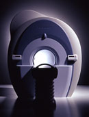
From Toshiba America Medical Systems Inc.;
With its high-field strength, the Vantage™ delivers the clinical capabilities and image quality expected by cardiologists, while simultaneously offering patients a more comfortable and non-invasive option, said Dane Peshe, director, MRI Business Unit, Toshiba America Medical Systems. Vantage™ supports a full complement of cardiovascular imaging studies, ranging from stroke evaluation to peripheral vascular imaging. Additionally, the ultra short bore design offers patients a greater feeling of openness that reduces claustrophobic sensations, while Toshiba's exclusive, patented Pianissimo™ technology reduces scan noise by as much as 90 percent for a more pleasant experience.'
Device Information and Specification CLINICAL APPLICATION Whole body CONFIGURATION Ultra short bore SE, FE, IR, FastSE, FastIR, FastFLAIR, Fast STIR, FastFE, FASE, EPI, SuperFASE; Angiography: 2D(gate/non-gate)/3D TOF, SORS-STC IMAGING MODES Single, multislice, volume study 32-1024, phase;; 64-1024, freq. POWER REQUIREMENTS 380/400/415/440/480 V COOLING SYSTEM TYPE Closed-loop water-cooled Liquid helium: approx. less than 0.05 L/hr Passive, active, auto-active | | | |
• View the DATABASE results for 'Vantage™' (2).
| | | | | | Further Reading: | Basics:
|
|
| |
| | | | |
| | | |
|
| |
 | Look
Ups |
| |


