Magnetic Resonance - Technology Information Portal Welcome to MRI Technology
Info
  Sheets

Out-
      side


 'Hardware' 
SEARCH FOR    
 
  2 3 5 A B C D E F G H I J K L M N O P Q R S T U V W X Y Z
Result : Searchterm 'Hardware' found in 1 term [] and 20 definitions []
previous     6 - 10 (of 21)     next
Result Pages : [1]  [2 3 4 5]
Searchterm 'Hardware' was also found in the following services: 
spacer
News  (3)  Resources  (4)  Forum  (3)  
 
Corrupted Data (Artifact)InfoSheet: - Artifacts - 
Case Studies, 
Reduction Index, 
etc.MRI Resource Directory:
 - Contrast Agents -
 
Quick Overview
Artifact Information
NAME
Corrupted data
DESCRIPTION
Incorrectly interpretation or display
REASON
Corrupted data
HELP
Save to a new or different media
An artifact on a MR image can appear when data read off an optical disc became corrupted. There two effects can be seen.
Firstly, Bands where the intensity has been incorrectly interpreted or secondly areas, where the horizontal position of the pixels has been incorrectly displayed. It is important to be able to differentiate between artifacts caused during a MRI scan, from those caused by the associated hardware of an imaging system.
mri safety guidance
Image Guidance
Review the hardware and store the images on a new disc.
spacer
 
Further Reading:
  Basics:
MRI Artifact Gallery
   by chickscope.beckman.uiuc.edu    
Searchterm 'Hardware' was also found in the following services: 
spacer
Radiology  (4) Open this link in a new windowUltrasound  (3) Open this link in a new window
Stuck ADC Bit ArtifactInfoSheet: - Artifacts - 
Case Studies, 
Reduction Index, 
etc.MRI Resource Directory:
 - Artifacts -
 
Quick Overview
Artifact Information
NAME
Stuck ADC bit
DESCRIPTION
Ghosting
REASON
Hardware problem
HELP
Data correction
This artifact is uncommon with modern MRI equipment, but possible. It can occur if there are bad memory locations or bad connectors in the parallel data bus of the computer.
mri safety guidance
Image Guidance
This artifact is the result of a hardware failure and must be addressed by a service representative.
spacer
 
Further Reading:
  News & More:
MRI Artifact Gallery
   by chickscope.beckman.uiuc.edu    
MRI Resources 
Spectroscopy pool - Non-English - Safety Training - Crystallography - Implant and Prosthesis pool - MR Myelography
 
Biograph mMR
 
www.healthcare.siemens.com/magnetic-resonance-imaging/mr-pet-scanner/biograph-mmr 
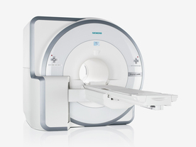
FDA cleared and CE Mark 2011.
The Biograph mMR has a fully-integrated design for simultaneous PET/MRI imaging. The dedicated hardware includes solid-state, avalanche photodiode PET detector and adapted, PET-compatible MR coils.
The possibility of truly simultaneous operation allows the acquisition of several magnetic resonance imaging (MRI) sequences during the positron emission tomography (PET) scan, without increasing the examination time.
See also Hybrid Imaging.
Device Information and Specification
CLINICAL APPLICATION
Whole Body
CONFIGURATION
Simultaneous PET/MRI
3 Tesla
Full range of MRI coils
CHANNELS
up to 32
PET ACQUISITION MODES
3D
MRI ACQUISITION MODES
2D/3D, spectroscopy;; iPAT, GRAPPA (k-space), noncontrast angiography, radial motion compensation
PET EFFECTIVE AXIAL FOV
26 cm (typical overlap 23%)
MRI FOV
A-P 45, R-L 50, H-F 50 cm
PET RING DIAMETER
65.6 cm
PATIENT SCAN RANGE
199 cm
HORIZONTAL SPEED
200 mmsec
TABLE CAPACITY
200 kg
PET DETECTOR
Solid state, 4032 avalanche photo diodes
DETECTOR SCINTILLATION MATERIAL
LSO, 28672 crystals
CRYSTAL SIZE
4 x 4 x 20 mm
MAGNET WEIGHT
9000 kg
DIMENSION H*W*D (gantry included)
335 x 230 x 242 cm (finshed covers)
5-GAUSS FRINGE FIELD
2.6 m / 4.6 m
CRYOGEN USE
Zero boil off rate, approx. 10 years
COOLING SYSTEM
PET system: water; MRI system: water
up to 200 T/m/s
MAX. AMPLITUDE
45 mT/m
Aautomatic, patient specific shim; active shim 3 linear and 5 non-linear channels (seond order)
POWER REQUIREMENTS
380 / 400 / 420 / 440 / 460 / 480 V, 3-phase + ground; Total system 110kW
spacer
 
Further Reading:
  Basics:
Performance Measurements of the Siemens mMR Integrated Whole-Body PET/MR Scanner
Friday, 11 November 2011   by jnm.snmjournals.org    
Global Trends in Hybrid Imaging
Monday, 1 November 2010   by pubs.rsna.org    
  News & More:
Positron Emission Tomographic Imaging in Stroke
Monday, 28 December 2015   by www.ncbi.nlm.nih.gov    
A world's first in imaging – integrated whole-body molecular MR system available for clinical use testing
Thursday, 18 November 2010   by www.siemens.com    
FDA Clears New System to Perform Simultaneous PET, MRI Scans
Friday, 10 June 2011   by www.prnewswire.com    
Frost & Sullivan Award Underlines Siemens Healthcare's Contribution to New Product Innovation in the North American Medical Imaging Market
Wednesday, 13 July 2011   by multivu.prnewswire.com    
Searchterm 'Hardware' was also found in the following services: 
spacer
News  (3)  Resources  (4)  Forum  (3)  
 
Blipped Phase Encoding
 
A strategy for incrementing the position of the k-space trajectory of an echo planar imaging (EPI) pulse sequence.
Echo planar imaging (EPI) uses a constant gradient amplitude in one direction. This, combined with an oscillating gradient system in the frequency encoding direction, produces a zigzag trajectory in k-space. In the blipped phase encoding variant of EPI, the k-space position in the phase encoded direction is incremented by gradient 'blips' of the appropriate area. These, when timed to occur during the reversals of the read-out gradient, produce a rectilinear path in k-space.
The artifacts in an EPI image can arise from both hardware and sample imperfections. These are most easily understandable from examination of the k-space trajectory involved, which is either a zigzag form (when using a constant phase encoding gradient) or a rastered zigzag (when the phase encoding is performed with small gradients at the end of each scan line, so-called 'blipped' EPI).
spacer
 
Further Reading:
  Basics:
Chapter 2 - Principles of Magnetic Resonance Imaging
   by www.fmrib.ox.ac.uk    
Searchterm 'Hardware' was also found in the following services: 
spacer
Radiology  (4) Open this link in a new windowUltrasound  (3) Open this link in a new window
Central Point ArtifactInfoSheet: - Artifacts - 
Case Studies, 
Reduction Index, 
etc.MRI Resource Directory:
 - Artifacts -
 
Quick Overview
Please note that there are different common names for this artifact.
Artifact Information
NAME
Central point, DC artifact, DC offset
DESCRIPTION
Bright spot
REASON
DC voltage offset
HELP
Call the service
This artifact appears as a bright spot (or zipper line) in the image center. Central point artifacts are caused by a DC offset in the hardware. MRI scanners normally offer a software compensation (DC correction, baseline correction) for prevention.
mri safety guidance
Image Guidance
Take care for a constant temperature. If the problem increases or keeps on existing, it should be addressed to the service.
spacer

• View the DATABASE results for 'Central Point Artifact' (4).Open this link in a new window

 
Further Reading:
  Basics:
Central Point Artifact
   by www.mritutor.org    
  News & More:
MRI Artifact Gallery
   by chickscope.beckman.uiuc.edu    
MRI Resources 
Fluorescence - Resources - MRI Technician and Technologist Schools - Patient Information - Cochlear Implant - Crystallography
 
previous      6 - 10 (of 21)     next
Result Pages : [1]  [2 3 4 5]
 Random Page
 
Share This Page
FacebookTwitterLinkedIn

MR-TIP    
Community   
User
Pass
Forgot your UserID/Password ?    


How AI will impact MRI :
only diagnostics 
saving time 
reducing cost 
makes planning obsolete 
reduce human knowledge 
not at all 

Look
      Ups


MR-TIP.com uses cookies! By browsing MR-TIP.com, you agree to our use of cookies.

Magnetic Resonance - Technology Information Portal
Member of SoftWays' Medical Imaging Group - MR-TIP • Radiology-TIP • Medical-Ultrasound-Imaging • 
Copyright © 2003 - 2024 SoftWays. All rights reserved. [ 19 April 2024]
Terms of Use | Privacy Policy | Advertising
 [last update: 2024-02-26 03:41:00]