 | Info
Sheets |
| | | | | | | | | | | | | | | | | | | | | | | | |
 | Out-
side |
| | | | |
|
| | | | | |  |
| | |
 |
| |
|
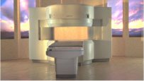
From Hitachi Medical Systems America Inc.;
the AIRIS II, an entry in the diagnostic category of open MR systems, was designed by Hitachi
Medical Systems America Inc. (Twinsburg, OH, USA) and Hitachi Medical Corp. (Tokyo) and is manufactured by the Tokyo branch. A 0.3 T field-strength magnet and phased array coils deliver high image quality without the need for a tunnel-type high-field system, thereby significantly improving patient comfort not only for claustrophobic patients.
Device Information and Specification
CLINICAL APPLICATION
Whole body
QD Head, MA Head and Neck, QD C-Spine, MA or QD Shoulder, MA CTL Spine, QD Knee, Neck, QD TMJ, QD Breast, QD Flex Body (4 sizes), Small and Large Extrem., QD Wrist, MA Foot and Ankle (WIP), PVA (WIP)
SE, GE, GR, IR, FIR, STIR, FSE, ss-FSE, FLAIR, EPI -DWI, SE-EPI, ms - EPI, SSP, MTC, SARGE, RSSG, TRSG, MRCP, Angiography: CE, 2D/3D TOF
IMAGING MODES
Single, multislice, volume study
TR
SE: 30 - 10,000msec GE: 20 - 10,000msec IR: 50 - 16,700msec FSE: 200 - 16,7000msec
TE
SE : 10 - 250msec IR: 10 -250msec GE: 5 - 50 msec FSE: 15 - 2,000
0.05 sec/image (256 x 256)
2D: 2 - 100 mm; 3D: 0.5 - 5 mm
Level Range: -2,000 to +4,000
POWER REQUIREMENTS
208/220/240 V, single phase
COOLING SYSTEM TYPE
Air-cooled
2.0 m lateral, 2.5 m vert./long
| | | |
• View the DATABASE results for 'AIRIS II™' (2).
| | | | | | |
|
| |
| | | | |
• View the NEWS results for 'Algorithm' (3).
| | |
• View the DATABASE results for 'Algorithm' (12).
| | | | | | | | | |
|
| |
| If the receiving RF coil is sensitive to tissue signal arising from outside the desired FOV, this undesired signal may be incorrectly mapped to a location within the image, a phenomenon known as aliasing. This is a consequence of the acquired k-space frequencies not being sampled densely enough, whereby portions of the object outside of the desired FOV get mapped to an incorrect location inside the FOV.
The sampling frequency should be at least twice the frequency being sampled. The maximum measurable frequency is therefore equal to half the sampling frequency. This is the so-called Nyquist limit. When the frequency is higher than the Nyquist limit, aliasing occurs.
A similar problem occurs in the phase encoding direction, where the phases of signal-bearing tissues outside of the FOV in the y-direction are a replication of the phases that are encoded within the FOV. This signal will be mapped, or wrapped back into the image at incorrect locations, and is seen as artifact.
See also Aliasing Artifact. | | | |
• View the DATABASE results for 'Aliasing' (19).
| | | | |  Further Reading: Further Reading: | News & More:
|
|
| | | |
|
| |
| Quick Overview
Please note that there are different common names for this MRI artifact.
DESCRIPTION
Image wrap around
Aliasing is an artifact that occurs in MR images when the scanned body part is larger than field of view ( FOV). As a consequence of the acquired k-space frequencies not being sampled densely enough, whereby portions of the object outside of the desired FOV get mapped to an incorrect location inside the FOV. The cyclical property of the Fourier transform fills the missing data of the right side with data from behind the FOV of the left side and vice versa. This is caused by a too small number of samples acquired in, e.g. the frequency encoding direction, therefore the spectrums will overlap, resulting in a replication of the object in the x direction.
Aliasing in the frequency direction can be eliminated by twice as fast sampling of the signal or by applying frequency specific filters to the received signal.
A similar problem occurs in the phase encoding direction, where the phases of signal-bearing tissues outside of the FOV in the y-direction are a replication of the phases that are encoded within the FOV. Phase encoding gradients are scaled for the field of view only, therefore tissues outside the FOV do not get properly phase encoded relative to their actual position and 'wraps' into the opposite side of the image.

Image Guidance
| | | |
• View the DATABASE results for 'Aliasing Artifact' (11).
| | | | | | |
|
| |
| Once hydrogen protons are placed in the presence of an external magnetic field, they align themselves in one of two directions, parallel or anti parallel to the net magnetic field.
The strength of the external magnetic field and the thermal energy of the atoms are the factors, which affect the direction of alignment of the hydrogen protons. The high-energy protons are strong enough to align themselves against or anti parallel to the magnetic field, whereas the lower energy protons will align themselves with or parallel to the magnetic field.
As the magnetic field increases, there are fewer protons, which are strong enough to align anti parallel to the magnetic field. There are always a larger number of protons aligned parallel with the magnetic field, so once the parallel and anti parallel protons cancel each other out, only the small number of low energy protons left aligned with the magnetic field create the overall net magnetization of the patient's body. | | | |
• View the NEWS results for 'Alignment' (1).
| | |
• View the DATABASE results for 'Alignment' (10).
| | | | | | | | | |
| | |
|
| |
 | Look
Ups |
| |


